Introduction
In this article we will be controlling the flow of Heat or Air Conditioning to a room. Lets say you have a room, like a spare bedroom, that you do not use that often. Does it really need to be 75 degrees like the rest of your house all year long? It seems like a waste to heat and cool a room you rarely use. What if you could adjust its temperature down in the winter to something like 60 degrees, that would certainly save some money on your heat bill. This setup will allow you to do that.
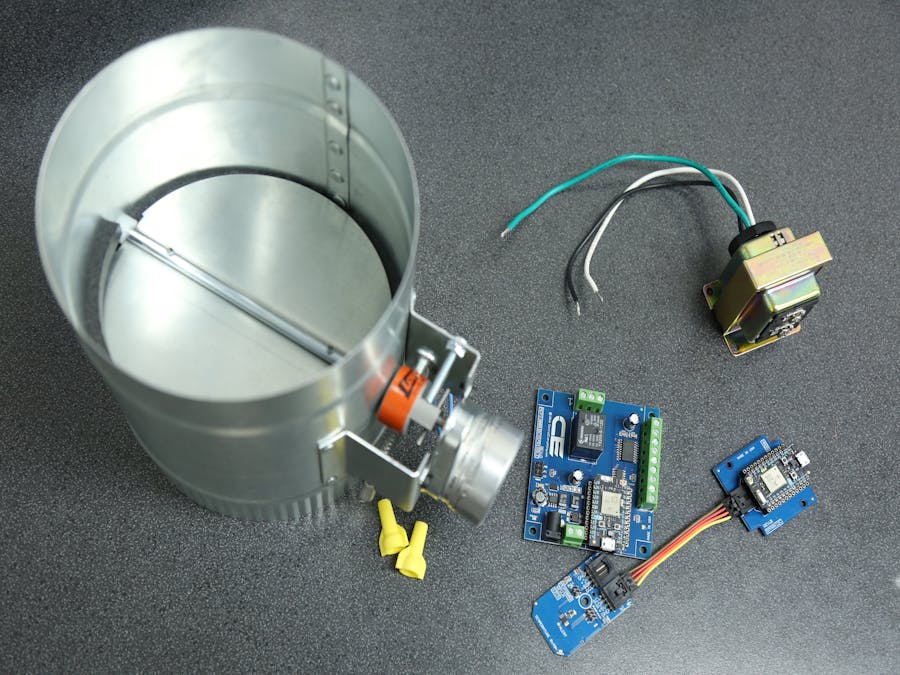
To accomplish this we will be electronically controlling a damper inside the duct that runs into a room to heat and cool the room. We will need a relay to open and close the damper along with a temperature sensor inside the room to monitor the room's temperature.
Wire it Up
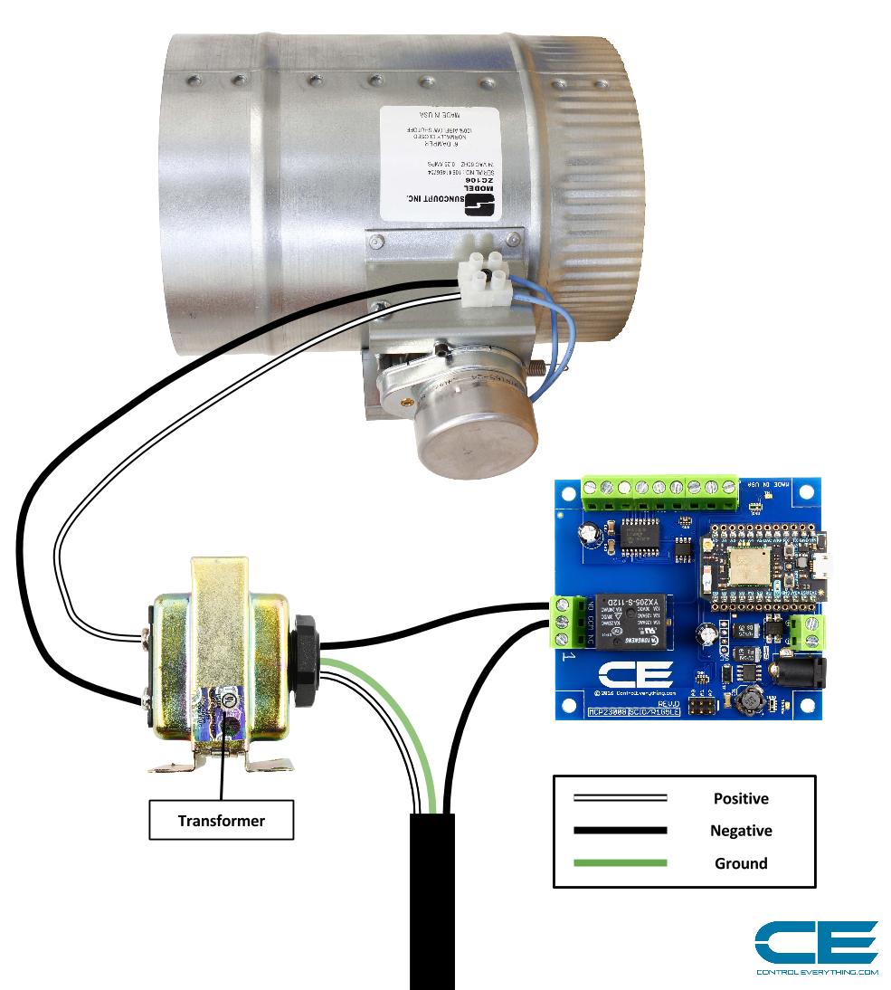
We need to connect 120VAC to the 24VAC transformer which will be used to operate the duct damper. We will use our 10 amp single relay to switch the hot leg of the 120VAC power supply source on and off to the 24VAC transformer. The output of the 24VAC transformer will be permanently connected to the Duct Damper and we will control it by connecting and disconnecting the 120VAC power supply source to the 24VAC transformer. Wire everything up as shown in the diagram above.
Setup Particle Photon modules and Particle Account.
Install the Particle Photon module into the 1 channel relay controller if it is not already.
Apply a regulated 12VDC power source to the 2.1mm barrel connector or power supply input screw terminals.
Install the second Particle Photon Module into the I2C Particle Photon Shield. Connect the I2C shield to the MCP9803 temperature sensor mini module with the included I2C cable. Finally apply power to the setup by connecting a USB Micro cable to the Particle Photon module. This will power both the Particle Photon module and the Mini Module Sensor.
Follow instructions here to setup your Particle Photon modules for your WiFi network and associate it with your Particle Account so we can interface with it and flash in firmware.
Flash Some Code
Open your browser and go to https://build.particle.io/build
Sign in with your Particle Account credentials.
- Open the devices list by clicking the devices icon on the left which looks like a target. Make sure to select the module which is installed in the I2C Shield and is connected to the temperature sensor mini module.
- Click the Libraries icon on the left which looks like a ribbon. Search under Community Libraries for MCP9803. Once found click to select it.
- On this Library make sure the duct-thermostat.ino tab is selected, then click the Use this Example button on the left to fork the library to your local repo.
- Once the Library is forked simply click the flash button in the upper left corner which looks like a lightning bolt. The firmware will now be flashed into your module, while flashing the module will flash a magenta LED, then it will reboot.
Once you are done with that it is time to flash the firmware into the relay board which will control the duct.
- Open the devices list by clicking the devices icon on the left which looks like a target. Make sure to select the module which is installed in the relay controller connected to the Duct Damper.
- Click the Libraries icon on the left which looks like a ribbon. Search under Community Libraries for NCD1Relay. Once found click to select it.
- On this Library make sure the duct-relay.ino tab is selected, then click the Use this Example button on the left to fork the library to your local repo.
- Once the Library is forked simply click the flash button in the upper left corner which looks like a lightning bolt. The firmware will now be flashed into your module, while flashing the module will flash a magenta LED, then it will reboot.
Both controllers are now running the appropriate firmware. We should now set our temperature and other parameters for the room.
Make it work
In your browser go to http://mobicle.io/
Sign in using your Particle account credentials.
Once loaded you should see a list of your Particle Devices.
Select the module installed in your I2C shield connected to the temperature sensor mini module.
Here you will see two functions setTemp and setSwing. Set temperature allows you to enter the temperature you would like the room to be set at. Go ahead click on setTemp and enter the temperature you would like to room set to.
Click on setSwing and enter the degrees of variance you would like to allow in the room. Most thermostats set this to 1 degree so if your thermostat is set to 75 degrees on heat the thermostat will not click on until the temperature gets down to 74. Using setSwing you can set that variance to anything you would like. Enter your value and send that.
On this screen you can view the current room temperature, the HVAC set temperature, the swing variance, and the HVAC Mode(AC or HEAT).
Now we need to set the HVAC Mode. To do this go back to the Device list in Mobicle. Click the Plus button next to Event Publishers to add a new button. Enter a name for the button like Turn on Heat or Switch to AC. Then for the Event Name enter HVAC_Mode. Now for the Event Data you need to pass HEAT to switch to heat mode or AC to switch to air conditioning mode. For TTL I recommend entering 120, that will be the amount of time the controller has to check this variable which should be plenty.
Everything should be working now.


Comments
Please log in or sign up to comment.