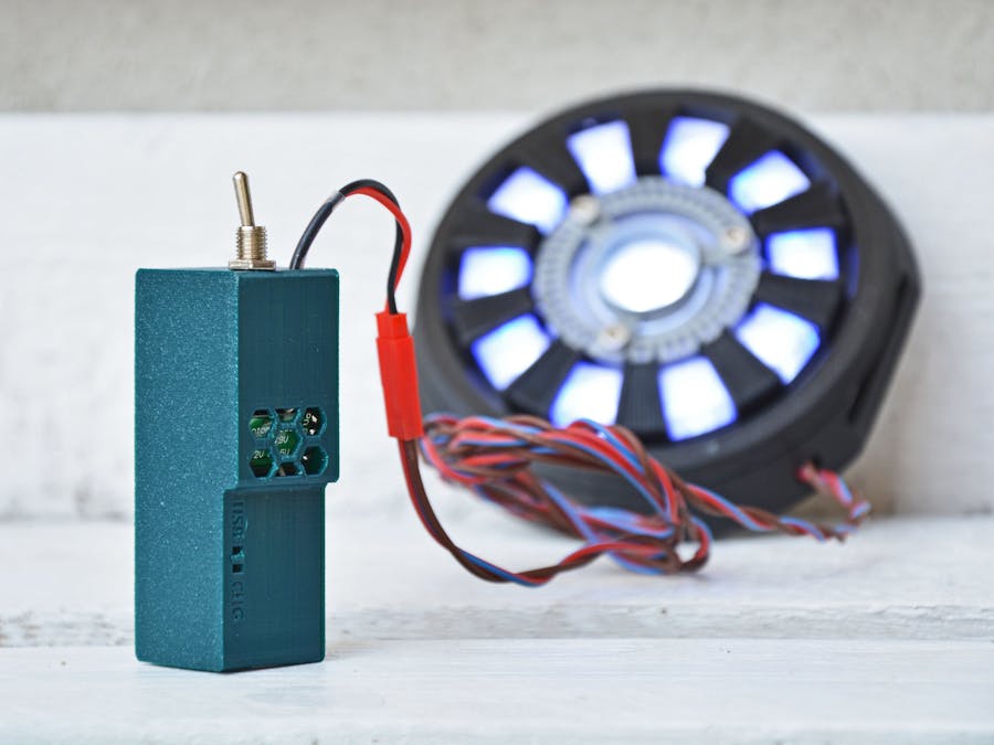
I built the Wearable Arc Reactor by Misha Tikh some times ago (it's the one appears in this project cover picture) and I wanted a reliable power supply for powering it. So this thing come in my mind: a small box having a 18650 Li-Ion cell with a booster module giving the 9V for powering leds and a recharging module with accessible USB:
There are some premises to say before starting to do a similar project:
- Li-Ion and Li-Po battery can be very dangerous if not properly handled, so I cannot take any responsibility for damages caused by this project.
- The Recharging module used here has NO protection: I choosed this for compactness purposes and because I had lot of them from some years ago, but is not the safest. Anyway I designed the enclosure around this specifical module.
- Would be better put this object in an explosive/fire-proof bag, expecially if used for cosplay purposes since it can be in contact with your body.
- Please use good cables: I used 22AWG silicon cables. Small cables can heat-up if current drawn is too high for them leading to fire or melting the box.
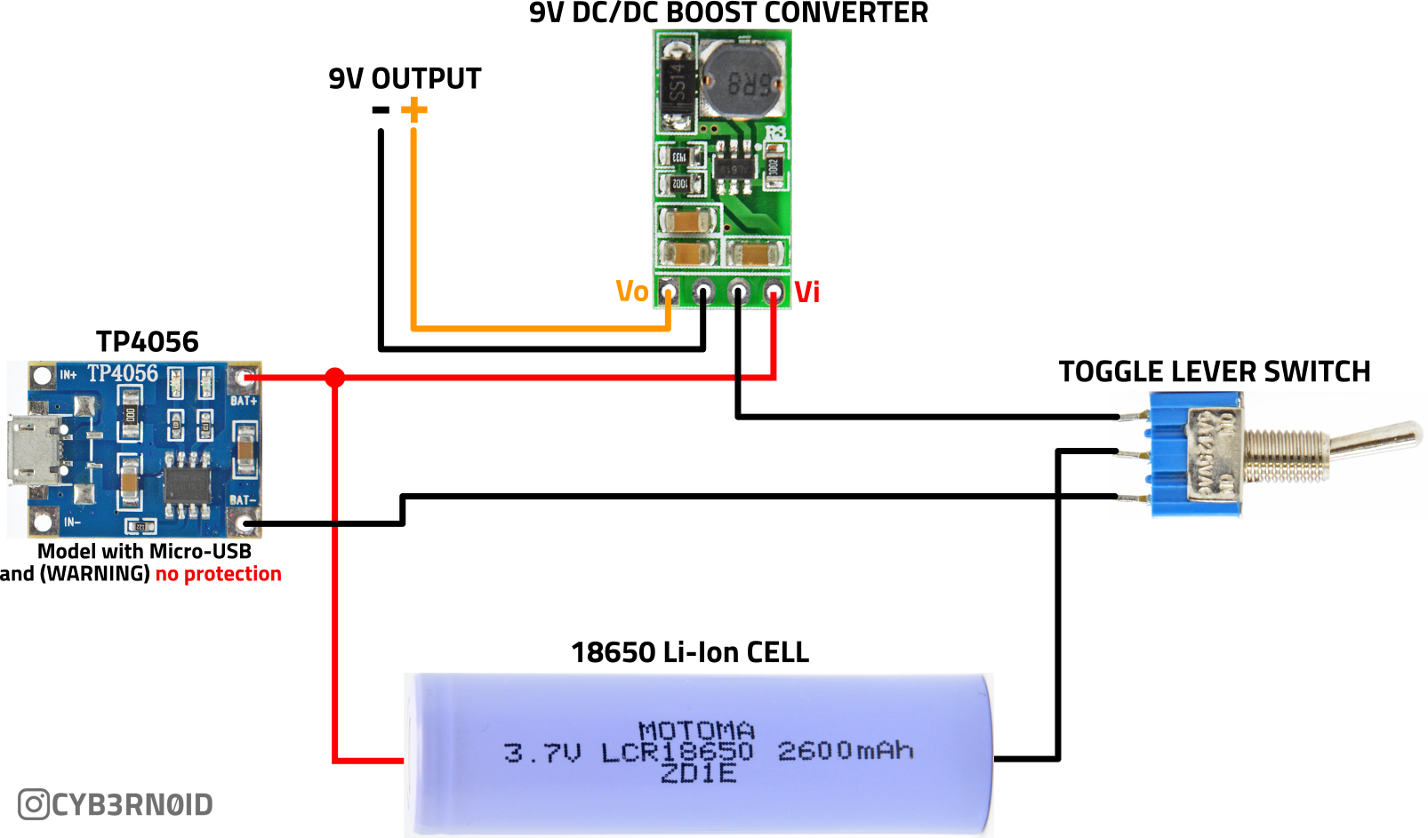
The circuit is very simple: the lever switch toggles the Li-Ion battery GND between a Booster module or the Charging module so those modules cannot work together: only one will be active depending on the switch position. The Battery positive terminal will be connected to both modules instead:
The booster module used outputs 9V, max 1A.
Box I designed can take only this specific module: it's good for my build of the Iron Man ARC reactor since leds in that project are connected in series of 3 or 4. I connected them in series of 4: this will lead to a lower brightness but also a lower power consumption not exceeding the 1A given by the choosed booster module.Mounting the circuit in the box
I've designed a 2-piece small box to be 3D-Printed (see the attachments). The main box body have 2 variants: they only differs for the vent holes: one has hexagon shaped holes and the other one has holes in form of tilted bar/slash bar. Print the one you like the most. Lid is the same for both boxes.
It's very important your printer is well calibrated since the lid will fit perfectly: if you find the lid too loose, you can wrap a rubber band around the box or use a small piece of tape.
You'll need also 2 small battery tabs I've not included in the material list: usually I recover them from my son's broken old toys:
Since room inside the box is very restricted (I tried to do it as small as possible), not all battery tabs can be good: in this case will be better having a 18650 cell having tabs (or, if you've a spot welder, you can attach Nickel tabs by yourself) so you can solder cables on tabs directly (not adviced soldering cables directly on the battery since can explode). Anyway print the box first so you can check components clearance.
Step1 - Solder cables on the toggle switch
Follow the pictures for dimensions of the cables:
Notice that the central cable have the tab for negative pole already soldered. If you are not using removable tabs, leave this tinned: you'll solder on the battery tab next.
Step2 - Solder cables on the BAT+ pad of the Charging module
Follow the picture:
As you can see, You'll solder 2 different length cables on the tab for the positive terminal. The longer one will be soldered on the BAT+ pad of the TP4056 module in the exact same orientation as in the picture (the red cable is soldered straight following the BAT- pad direction).
STEP3 - Prepare the output cable
For this kind of project I like to use JST-RCY connectors. I bought a kit and I crimp cables using the Preciva crimping tool I listed. Those kind of connector are commonly used for LED stripes and can tolerate up to 3A DC or AC current up to 250V so are very safe for this kind of project.
If you plan to use this connector, always use the socket contact (called SYF) in the plug housing on the powering device and the pin contact (called SYM) in the receptacle housing on the powered device. I use this combination since if the powering device, if leaved unconnected and turned on, having the socket is less susceptible to short circuits while the pin contact are more easy to short
For this cable, cut wires to the length you prefer.
STEP4 - Insert the lever switch
Insert the lever switch in his hole this way (lever turned up and shorter wire up):
Then screw the switch:
And attach the negative battery tab on the wall on the same side of the toggle switch using double-sided tape:
STEP5-Attach the TP4056 battery charger module
As said previously, this box is made for the TP4056 charging module having the micro-USB connector and not having the battery protection, so other models will not fit.
Pass the longer cable of the switch (the one you cut in 47mm and now facing down the box) in the holes making it arrive in the socket dedicated to the charging module:
Solder that cable on the BAT- pad of the charging module:
Turn the module so the component parts is facing the external wall, so the 2 SMD leds can go through their holes and push module down until you hear the "click" of the usb connector entering his hole:
There is also a small tab inside the charging module socket I've added for not make the board moving backward when you connect the USB cable, so check the board is perfectly aligned with internal wall. Now attach the positive tab for the cell on the wall using double-sided tape:
STEP6 - Attach the Booster Module
Pass the output cable you've prepared in the STEP 3 through the output hole and internal hole until it arrives in the central socket:
Now you must take a lot of care soldering cables on the booster module! Booster module has pads identified on the back of the board.
- RED (+) output wire has to be soldered on the Vo (V out) pad
- BLACK (-) output wire has to be soldered on the GND pad near the Vo
- RED (+) wire from the positive battery tab has to be soldered on the Vi (V in) pad
- remaining wire from the toggle switch (-) will go on the remained pad: GND near the Vi pad:
As you see from the picture, the back of the board will face the venting holes.
Now you can push down the module making attention to the cables:
At this time, first to install the battery, check connections using a multimeter. Check for short circuits mainly. If you followed the steps and you've not moved the switch, at this time the circuit is in OFF (= charging) state: the GND from battery is connected to the TP4056 module and so is disconnected from the Booster module.
STEP7 - Insert the cell and finish
After you checked with a multimeter is all ok, you can insert the 18650 cell:
And then you can apply the lid:
As said above, if your lid is too lose, wrap a rubber band or some tape around the box.


Comments
Please log in or sign up to comment.