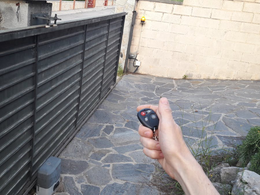
Well, the story began one day when I arrived at home and I realized that the remote controller of the sliding door was not working. "The batteries!" I thought, but no, this was not the reason. I investigated a little and what a surprise when I removed the cover of the door motor: a little lizard was literally carbonized in a tiny space between the electronic control board and the plastic support (by the way, I am not going to upload images from that horrendous scene). I guess that the little reptile touched the 220V fastons and produced a short circuit. The result was its death and all the circuit became burnt.
I have removed from the board some components that I could save for using in my projects, but you can see in this photo how it ended up.
In that very moment I decided that this might be the perfect excuse for make an Arduino project and a complete rebuild of the control unit.
WARNINGFor this project you will have to deal with components connected to 220V directly (or 110V). Take in account that this may be dangerous if you are not very skilled with this sort of installations. Please, be careful and proceed with caution. Always perform a simulation before connecting to the actual motor circuitry.
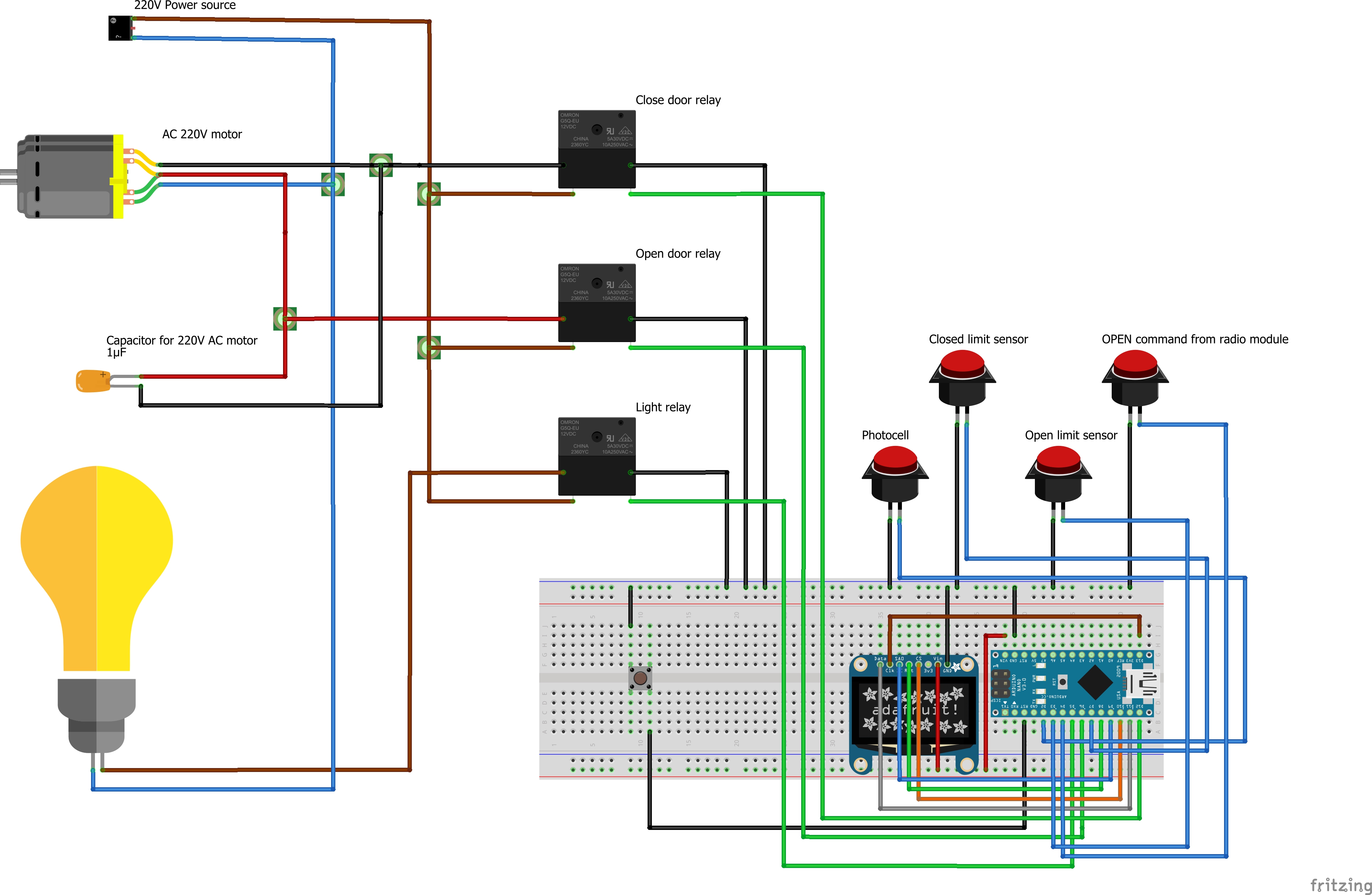
Components & CircuitryThe project is divided in some parts, but what I present here is the Arduino circuitry that controls the rotation of the motor and the signaling light, and takes into account the status of the limit switch sensors and a safety photocell.
At first, you could think that it is easy to build and program, but I can assure you that I had to overcome a lot of difficulties that made this project so exciting.
Other important components for the whole project are:
- Electric 220V motor and physical guides and mechanisms: these were not affected by the lizard's action.
- Remote radio receiver to issue the "Open" command: I have used a commercial ready made unit that included the remote controllers and the receiver.
- 220V relays to support the high current used by the motor.
- Main control unit made with Arduino Nano and other compatible accessories such as OLED display and relays module. This is what I show you in this portal.
I also have added some improvements and several automated actions that were not included in the commercial original control unit.
Pinouts for This ProjectThe following information sumarizes the pins of the components and how to connect them:
As you can see, for this project I have used an OLED display directly attached to the board. Under normal working conditions, this display is located inside the protection cover of the mechanism and the electronics. So that, you are not able to see it. In fact, this display is intended to be used used only to check the status of the components while you adjust settings and do a fine tunning to the code (max time adjustement for instance).
The information provided by this display could also have been sent to the serial port and checked from a laptop with the Arduino IDE software, but I find that this little display is a cool way to operate the unit without the need of using any laptop or additional device.
The displayed information in the OLED is the following:
- Phase of the code being executed (Opening door, closing door, waiting for "Open" command, main loop, ...)
- Elapsed time for main actions (Opening, waiting before closing again and closing)
- Photocell status (active when someone or something is in the closing path)
- CLOSED limit sensor status (active when the door is fully closed)
- OPENED limit sensor status (active when the door is fully Opened)
- OPEN command signal (active when the remote controller is pressed and the radio module activate a relay)
Note: The OLED display that I am using is 0.96 inches and has a resolution of 128 x 64 pixels. This display can use I2C or SPI to communicate to the control device (Arduino Nano in this case) and I am using SPI (Serial Peripheral Interface).
The following flow charts sumarize the software code in a readable way:


_3u05Tpwasz.png?auto=compress%2Cformat&w=40&h=40&fit=fillmax&bg=fff&dpr=2)
Comments