The scorching days of summer are winding down and the electric bills have cost you your right arm so now it is time to find a way to stay cool without an air conditioner. The first thing that comes to mind is some kind of fan.
Maybe you don't want all of the breeze to be right in your face but prefer it to be more intermittent. Now what comes to mind? For me, it's an oscillating fan!
This project uses Simulink and Stateflow to create an Arduino-based oscillating fan.
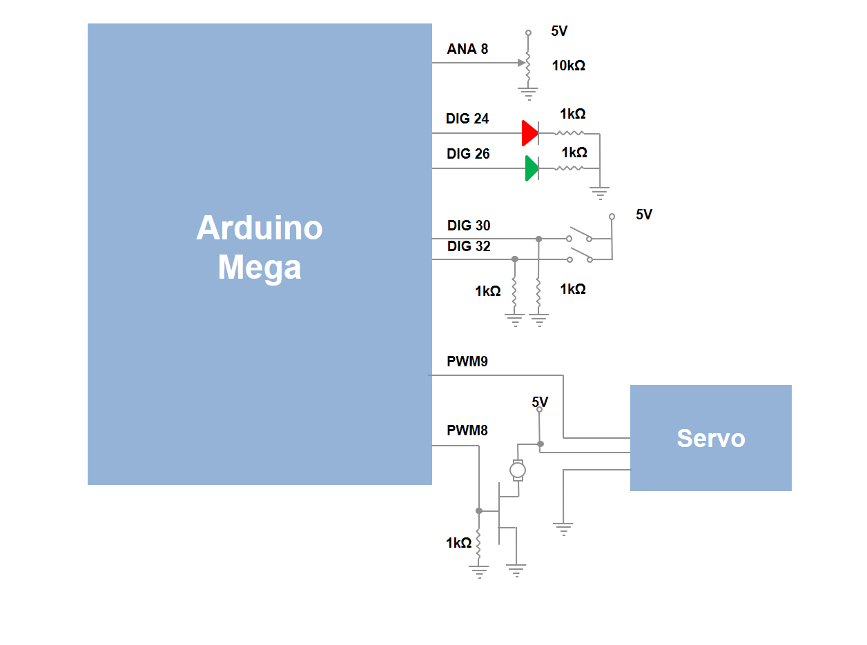
Overview:You can wire the hardware using the circuit schematic below or you can follow the steps detailed here.
- Mount the core-less motor on top of the servo motor.
- Connect analog pin 8 to the output of the potentiometer. The two reference pins should be connected to 5V and the Arduino's ground.
- Connect digital pin 24 to the cathode of the red LED. A 1kΩ pull-down resistor should connect the anode to the ground.
- Connect digital pin 26 to the cathode of the green LED. A 1kΩ pull-down resistor should connect the anode to the ground.
- Connect digital pin 30 and a 1kΩ pull-down resistor to one pin of the first push button and the other pin to 5V.
- Connect digital pin 32 and a 1kΩ pull-down resistor to one pin of the second push button and the other pin to 5V.
- Connect PWM pin 9 to the signal pin of the servo motor, 5V to the power pin and ground to the ground pin.
- Connect PWM pin 8 and a 1kΩ pull-down resistor to the gate of the IRF510. The source of the IRF510 should be connected to ground.
- Connect the negative pin of the core-less motor to the drain of the IRF510 and connect the positive pin to 5V.
Software:
The fan has two main modes: fanning mode and oscillation mode.
View of the Stateflow Logic
- Fanning mode: the chart checks to see if the user has pressed the button to turn on the fan. If the button has been pressed, the program waits for it to debounce (to be released) and then it turns the fan on at the speed specified by the potentiometer. The fan remains on until the button is pressed again.
- Oscillation mode: the chart checks to see if the fan button has been pressed (or if the fan is currently on) and that the oscillation button has been pressed. If this is the case, once the buttons debounce, the fan begins to rotate in the counterclockwise direction. Once it has reached its counterclockwise boundary value, it rotates back in the clockwise direction until it reaches its clockwise boundary value. The fan oscillates between these two values until the fan is turned off or the oscillation button is pressed again.
Additional Notes:
- If the polarities of the hardware are not correct, the demo may not work.
Documentation and Demonstration
To download the files for this project and see a video of the project in action, you can go to the following link:
https://www.mathworks.com/matlabcentral/fileexchange/58440-creating-an-oscillating-fan-using-simulink-and-arduino


_wzec989qrF.jpg?auto=compress%2Cformat&w=48&h=48&fit=fill&bg=ffffff)


Comments
Please log in or sign up to comment.