I decided to make a digital wall clock after I found an aluminum profile in my basement, using an Arduino Mega 2560, DS3231 RTC, 5054 LED strip, and IRFZ44N MOSFET transistor to realize my idea.
5054 LED strip: You can order it from here.
Order IRFZ44N from here.
Order DS3231 from here.
You can order a better aluminum profile from here
- Phisical works:
The clock background I've cut from wood. The dimensions of background: 800 x 300 x 70 (mm)
Each length of aluminum profile for segment: 100 mm x 18 mm wide. And for dots about: 27mm.
So for segment, you can cut and stick on 12 LEDs (or 3 section) of particular LED strip. And for dots display 3 LEDs (or 1 section).
After that I painted the background in black.
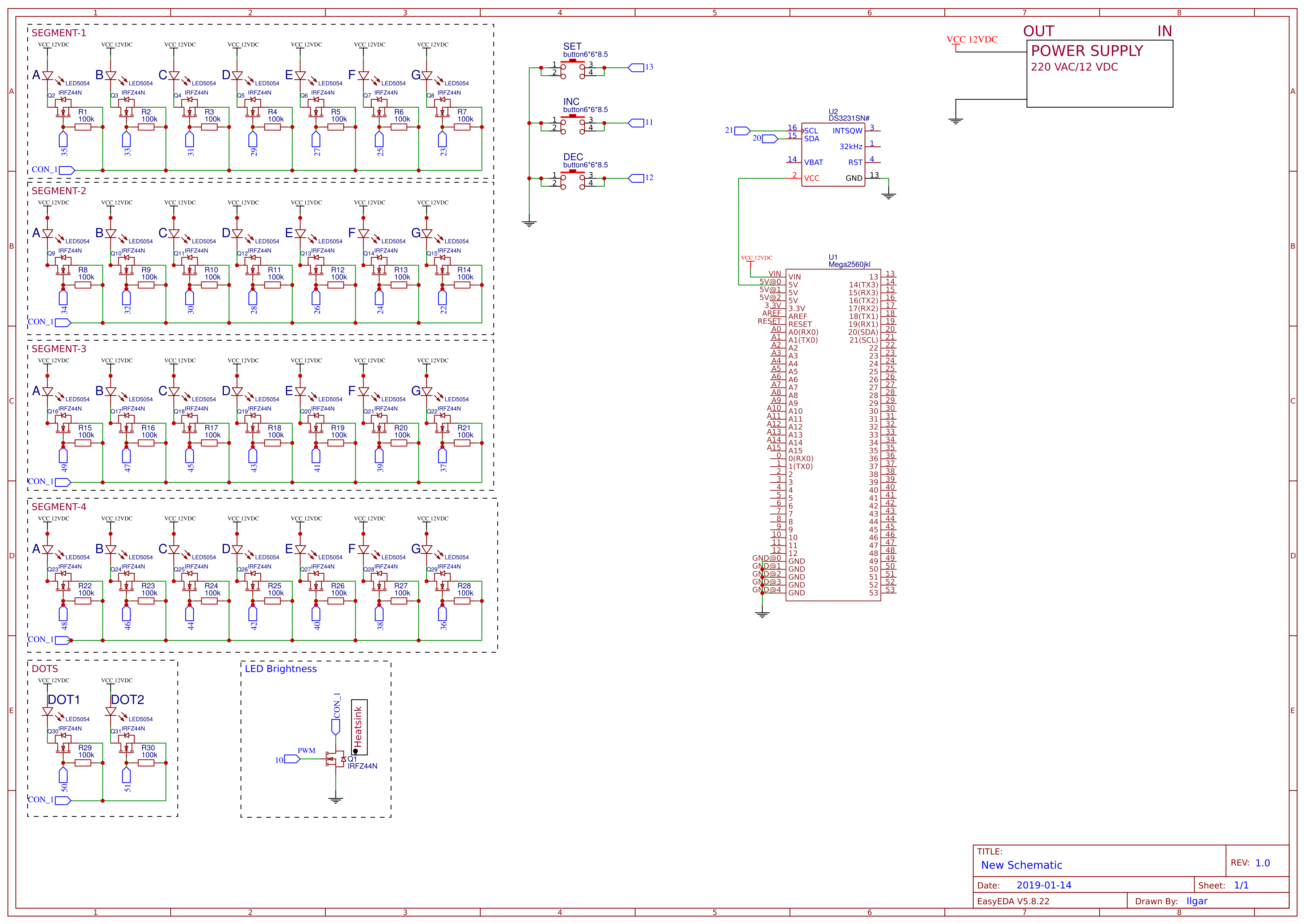
- Schematic connection
- Code:
The code seems a lite bit complicated but it a quite simple.
First I made an Excel form to get a picture how it will be. For example if I get number 4 from RTC, for the segment it will be like 0110011-ABCDEFG. 51 in DEC
So I return the 51 in DEC from clock_array[] which located in 4th place and read it with bitRead() function and send it to outputs. I selected outputs pins like that for easy to connection and maintenance for each segment to Mega 2560 board.
I used 8-bit PWM for brighness control over PIN 10 (Timer 2). So you can also regulate the brightness 0-255 as you wish. Used EEPROM memory to remember PWM value.
Also clock displays the DS3231 board temperature between 30-32 seconds of each minute.
SET button logic:
- button SET (no press): Clock in normal mode
- button SET (first press): Adjusting Hour
- button SET (second press): Adjusting Minute
- button SET (third press): Adjusting PWM value
- button SET(4 th press): Saving all parameter and returns to normal mode
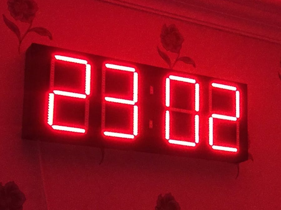
View on the wall:
CODE:
#include <EEPROM.h>
#include <Sodaq_DS3231.h>
#include <Wire.h>
/*
*
*     Output A frequency: 16 MHz / 8 / 256 = 7812.5Hz//Prescaler is 8//CS21 is ON
   Output A duty cycle: (180+1) / 256 = 70.7%
   Output B frequency: 16 MHz / 8 / 256 = 7812.5Hz //Prescaler is 8//CS21 is ON
   Output B duty cycle: (50+1) / 256 = 19.9%
The output frequency is the 16MHz system clock frequency, divided by the prescaler value (64), divided by the 256 cycles it takes for the timer to wrap around.
Note that fast PWM holds the output high one cycle longer than the compare register value.
*/
boolean set_button;//setting button
boolean dec_button;//decrease button
boolean inc_button;//increase button
boolean trig_set_button;
boolean trig_dec_button;
boolean trig_inc_button;
boolean trig_writing;
boolean trig_dots = false;
boolean trig_temp;
int clock_array[10]={126,48,109,121,51,91,95,112,127,123};//from 0 to 9
int seg1_array[7] = {23,25,27,29,31,33,35};//G,F,E,D,C,B,A
int seg2_array[7] = {22,24,26,28,30,32,34};//G,F,E,D,C,B,A
int seg3_array[7] = {37,39,41,43,45,47,49};//G,F,E,D,C,B,A
int seg4_array[7] = {36,38,40,42,44,46,48};//G,F,E,D,C,B,A
unsigned int tm_second, tm_minute, tm_hour, tm_day, tm_month, tm_year;
uint32_t old_ts; //RTC data//
int h_t;
int h_d;
int m_t;
int m_d;
int pwm_h;//hundred
int pwm_t;//ten
int pwm_d;
short previous_second;
float temp;
unsigned int temp_int;
short temp_1;
short temp_2;
short temp_3;
short temp_4;
unsigned int pwm_brightness;
int mode = 0;
void setup() {
 //INPUTS//
 pinMode(11, INPUT_PULLUP);
 pinMode(12, INPUT_PULLUP);
 pinMode(13, INPUT_PULLUP);
 //PWM SETUP//
 pinMode(10, OUTPUT); //OCR2A PIN 10 for MEGA2560//PIN 3 for UNO
 pinMode(9, OUTPUT);//OCR2B PIN 9 for MEGA2560//PIN 11 for UNO
 TCCR2A = _BV(COM2A1) | _BV(COM2B1) | _BV(WGM21) | _BV(WGM20);
 TCCR2B = _BV(CS21);//7745Hz
 pwm_brightness = EEPROM.read(0);
 //Clock SETUP//
 Wire.begin(); //enable I2C//
 rtc.begin();  //enable RTC//
 //OUTPUTS//
 pinMode(22, OUTPUT);
 pinMode(23, OUTPUT);
 pinMode(24, OUTPUT);
 pinMode(25, OUTPUT);
 pinMode(26, OUTPUT);
 pinMode(27, OUTPUT);
 pinMode(28, OUTPUT);
 pinMode(29, OUTPUT);
 pinMode(30, OUTPUT);
 pinMode(31, OUTPUT);
 pinMode(32, OUTPUT);
 pinMode(33, OUTPUT);
 pinMode(34, OUTPUT);
 pinMode(35, OUTPUT);
 pinMode(36, OUTPUT);
 pinMode(37, OUTPUT);
 pinMode(38, OUTPUT);
 pinMode(39, OUTPUT);
 pinMode(40, OUTPUT);
 pinMode(41, OUTPUT);
 pinMode(42, OUTPUT);
 pinMode(43, OUTPUT);
 pinMode(44, OUTPUT);
 pinMode(45, OUTPUT);
 pinMode(46, OUTPUT);
 pinMode(47, OUTPUT);
 pinMode(48, OUTPUT);
 pinMode(49, OUTPUT);
 pinMode(50, OUTPUT);//upside dot
 pinMode(51, OUTPUT);//downside dot
}
void loop() {
set_button = !digitalRead(13);
dec_button = !digitalRead(12);
inc_button = !digitalRead(11);
if(set_button==false){trig_set_button = false;}
if(set_button==true&&trig_set_button==false)
{
 mode++;
 if(mode>3){mode = 0;}//only 3 modes enabled
 trig_set_button = true;
}
if(previous_second!=tm_second)
{
  trig_dots = !trig_dots;
 previous_second = tm_second;
}
///////////////////////////////////
//Buttons Mode configuration//
switch (mode)
{
 case 0:
 break;
 case 1:
    trig_writing = true;//enabling this trig to write data one shoot
    if(dec_button==false){trig_dec_button = false;}
    if(dec_button==true&&trig_dec_button==false)
    {
     if(tm_hour>0&&tm_hour<=24){tm_hour--;}
     trig_dec_button = true;
    }
    if(inc_button==false){trig_inc_button = false;}
    if(inc_button==true&&trig_inc_button==false)
    {
     if(tm_hour>=0&&tm_hour<24){tm_hour++;}
     trig_inc_button = true;
    }
 break;
 case 2:
    if(dec_button==false){trig_dec_button = false;}
    if(dec_button==true&&trig_dec_button==false)
    {
     if(tm_minute>0&&tm_minute<=59){tm_minute--;}
     trig_dec_button = true;
    }
    if(inc_button==false){trig_inc_button = false;}
    if(inc_button==true&&trig_inc_button==false)
    {
     if(tm_minute>=0&&tm_minute<59){tm_minute++;}
     trig_inc_button = true;
    }
 break;
 case 3:
    if(dec_button==false){trig_dec_button = false;}
    if(dec_button==true&&trig_dec_button==false)
    {
     if(pwm_brightness>0&&pwm_brightness<=255){pwm_brightness--;}
     trig_dec_button = true;
    }
    if(inc_button==false){trig_inc_button = false;}
    if(inc_button==true&&trig_inc_button==false)
    {
     if(pwm_brightness>=0&&pwm_brightness<255){pwm_brightness++;}
     trig_inc_button = true;
    }
 break;
}
if(mode==0){
       //RTC//
   if(trig_writing==true)//writing in one shoot mode
   {
     DateTime dt(2019, 2, 19, tm_hour, tm_minute, 0, 0);
     rtc.setDateTime(dt);
     EEPROM.write(0, pwm_brightness);
     delay(50);
     trig_writing = false;
   }
 rtc.convertTemperature();
 if(trig_temp==false){temp = rtc.getTemperature();}//not to update temperature value when display the temp
 DateTime now = rtc.now(); //get the current date-time
 uint32_t ts = now.getEpoch();
 if (old_ts == 0 || old_ts != ts) {
 old_ts = ts;
 tm_second = now.second();
 tm_minute = now.minute();
 tm_hour = now.hour();
 tm_day = now.date();
 tm_month = now.month();
 tm_year = now.year();
 }
}//end if mode
//separating hour and minute//
 h_t = (tm_hour % 100)/10;
 h_d = tm_hour % 10;
 m_t = (tm_minute % 100)/10;
 m_d = tm_minute % 10;
 //////////////////////
 //separating pwm_brightness//
 pwm_h = (pwm_brightness % 1000)/100;
 pwm_t = (pwm_brightness % 100)/10;
 pwm_d = pwm_brightness % 10;
 //////////////////////
 //separating temperature//
 temp_int = temp * 100;//convert point float to integer
 temp_1 = (temp_int % 10000)/1000;
 temp_2 = (temp_int % 1000)/100;
 temp_3 = (temp_int % 100)/10;
 temp_4 = temp_int % 10;
 //////////////////////
for(int i=0;i<7;i++)
{
 switch (mode)
 {
   case 0://normal time mode
 if(tm_second<30||tm_second>32)//display the DS3231 temperature between 30 and 32 second of each minute
 {
   trig_temp = false;
 if(tm_hour>9)
 {
  digitalWrite(seg1_array[i], bitRead(clock_array[h_t], i));//Output of 1 segment
  digitalWrite(seg2_array[i], bitRead(clock_array[h_d], i));//Output of 2 segment
 }else
 {
  digitalWrite(seg1_array[i], bitRead(clock_array[0], i));//Output of 1 segment
  digitalWrite(seg2_array[i], bitRead(clock_array[tm_hour], i));//Output of 2 segment
 }
 if(tm_minute>9)
 {
  digitalWrite(seg3_array[i], bitRead(clock_array[m_t], i));//Output of 3 segment
  digitalWrite(seg4_array[i], bitRead(clock_array[m_d], i));//Output of 4 segment
 }else//displaying DS3231 temperature
 {
  digitalWrite(seg3_array[i], bitRead(clock_array[0], i));//Output of 3 segment
  digitalWrite(seg4_array[i], bitRead(clock_array[tm_minute], i));//Output of 4 segment
 }
  digitalWrite(50, trig_dots);
  digitalWrite(51, trig_dots);
 }else
 {
   trig_temp = true;
   digitalWrite(seg1_array[i], bitRead(clock_array[temp_1], i));//Output of 1 segment
   digitalWrite(seg2_array[i], bitRead(clock_array[temp_2], i));//Output of 2 segment
   digitalWrite(seg3_array[i], bitRead(clock_array[temp_3], i));//Output of 3 segment
   digitalWrite(seg4_array[i], bitRead(clock_array[temp_4], i));//Output of 4 segment
   digitalWrite(50, LOW);
   digitalWrite(51, HIGH);
 }
 break;
 case 1://adjusting hour
 if(tm_hour>9)
 {
  digitalWrite(seg1_array[i], bitRead(clock_array[h_t], i));//Output of 1 segment
  digitalWrite(seg2_array[i], bitRead(clock_array[h_d], i));//Output of 2 segment
 }else
 {
  digitalWrite(seg1_array[i], bitRead(clock_array[0], i));//Output of 1 segment
  digitalWrite(seg2_array[i], bitRead(clock_array[tm_hour], i));//Output of 2 segment
 }
  digitalWrite(seg3_array[i], 0);//OFF the 3 segment
  digitalWrite(seg4_array[i], 0);//OFF the 4 segment
  digitalWrite(50, 0);//OFF the dot
  digitalWrite(50, 0);//OFF the dot
 break;
 case 2://adjustng minute
 if(tm_minute>9)
 {
  digitalWrite(seg3_array[i], bitRead(clock_array[m_t], i));//Output of 3 segment
  digitalWrite(seg4_array[i], bitRead(clock_array[m_d], i));//Output of 4 segment
 }else
 {
  digitalWrite(seg3_array[i], bitRead(clock_array[0], i));//Output of 3 segment
  digitalWrite(seg4_array[i], bitRead(clock_array[tm_minute], i));//Output of 4 segment
 }
  digitalWrite(seg1_array[i], 0);//OFF the 1 segment
  digitalWrite(seg2_array[i], 0);//OFF the 2 segment
  digitalWrite(50, 0);//OFF the dot
  digitalWrite(50, 0);//OFF the dot
 break;
 case 3://adjusting pwm
  if(pwm_brightness>99)
 {
   digitalWrite(seg1_array[i], LOW);//Output of 1 segment
   digitalWrite(seg2_array[i], bitRead(clock_array[pwm_h], i));//Output of 2 segment
   digitalWrite(seg3_array[i], bitRead(clock_array[pwm_t], i));//Output of 3 segment
   digitalWrite(seg4_array[i], bitRead(clock_array[pwm_d], i));//Output of 4 segment
 }else if(pwm_brightness>9&&pwm_brightness<=99)
 {
   digitalWrite(seg1_array[i], LOW);//Output of 1 segment
   digitalWrite(seg2_array[i], LOW);//Output of 2 segment
   digitalWrite(seg3_array[i], bitRead(clock_array[pwm_t], i));//Output of 3 segment
   digitalWrite(seg4_array[i], bitRead(clock_array[pwm_d], i));//Output of 4 segment
 }else if(pwm_brightness<=9)
 {
   digitalWrite(seg1_array[i], LOW);//Output of 1 segment
   digitalWrite(seg2_array[i], LOW);//Output of 2 segment
   digitalWrite(seg3_array[i], LOW);//Output of 3 segment
   digitalWrite(seg4_array[i], bitRead(clock_array[pwm_d], i));//Output of 4 segment
 }
 digitalWrite(50, 0);//OFF the dot
 digitalWrite(51, 0);//OFF the dot
 break;
 }//end switch(mode)
}//end for
 OCR2A = pwm_brightness;
 OCR2B = 5;//has no effect
}//end loop


_wzec989qrF.jpg?auto=compress%2Cformat&w=48&h=48&fit=fill&bg=ffffff)


_1x_bGT19vVAby.png?auto=compress%2Cformat&w=40&h=40&fit=fillmax&bg=fff&dpr=2)
Comments
Please log in or sign up to comment.