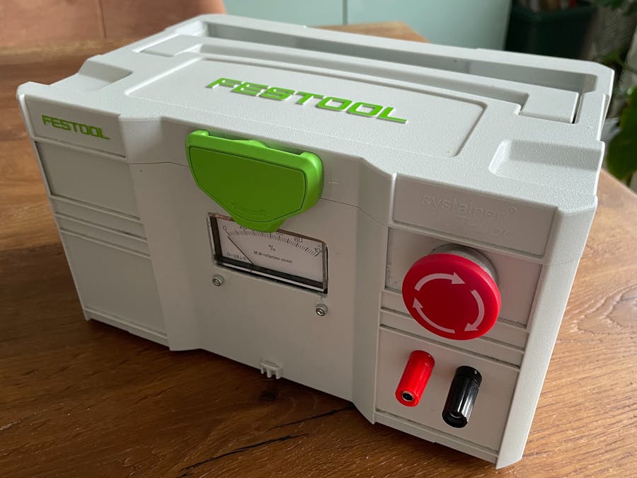
I am a huge fan of Festool Systainer boxes and have been collecting them for over 10 years. They are practical for storage, stackable and transportable in the block. For many Arduino projects I often look for suitable boxes to store the electronics - the Systainer Mini are perfect for this. Inexpensive, high-strength, thermally resistant and offer all the other advantages of the larger boxes.
For my Arduino projects I would like to use these boxes in the future and have started with a first project - the PowerBox.
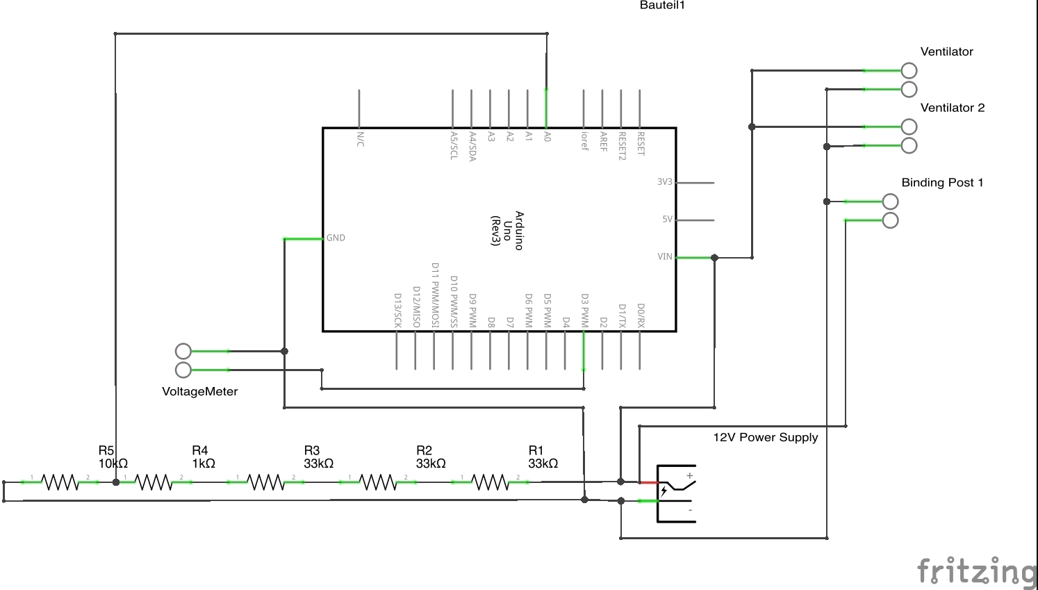
The PowerBox includes a 12V power supply and a voltmeter that indicates whether 12V or less is present. The voltage measurement itself is done via two resistors (Voltage divider) and the Arduino analog input and the voltage meter is controlled via PWM. To use the 12V for projects, practical binding posts were used (called laboratory terminals or banana plugs). For safety there is an emergency stop switch that disconnects the 230V supply to the power supply. The 230V cable can be conveniently transported in the box when not needed.
I use the box now for example for my CNC milling machine or other Arduino projects.
Build LogWhen building the box, I wanted to create a way to show that the 12V is really present. Only one LED would not have been enough for me.
Years ago I have already rescued this beautiful VoltageMeter from the waste and can now use this. It normally shows energy in percent but I use it now for voltage. 100% corresponds to 12V, this is controlled by a PWM pin (pin 3 on the Arduino). In essence it is a simple electric motor that is controlled to display and hold each.
First I measured the box and made a wooden plate to hold the power supply, Arduino and the PCB. Then I milled the passages for the VoltageMeter, Binding Posts and the emergency stop switch in the housing with a Dremel. The good thing about the Systainer is that it's made of a thermoplastic, so it's very easy to cut into it - wait a bit and then just snap the burrs off when they get hard. For the 230V connection I installed an adapter in the back. After that everything was wired and the Arduino code was adapted. The Arduino Uno itself is powered by the 12V power supply. I tried the circuit before on a breadboard (but unfortunately no more photos of it).
For the volt measurement logic I used also the tutorial from Arduino Project Hub considering two resistors and measure the by voltage divider.


_ztBMuBhMHo.jpg?auto=compress%2Cformat&w=48&h=48&fit=fill&bg=ffffff)


Comments
Please log in or sign up to comment.