


Hardware components | ||||||
 |
| × | 1 | |||
 |
| × | 1 | |||
 |
| × | 256 | |||
 |
| × | 64 | |||
 |
| × | 512 | |||
 |
| × | 4 | |||
| × | 1 | ||||
| × | 999 | ||||
Software apps and online services | ||||||
 |
| |||||
| ||||||
Hand tools and fabrication machines | ||||||
 |
| |||||
 |
| |||||
 |
| |||||
 |
| |||||
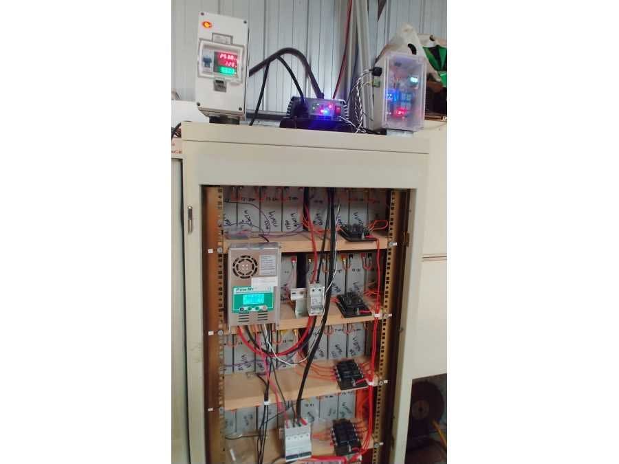
I came across literally a ton of used batteries and an old cabinet, before I knew it the project had a life of its own. Add an inverter, charger and circuit breakers. A few hours of very repetitive labor and "presto", I could load shift several Kilowatt hours of solar power from day to night. It's all charged with roof mounted PV panels re-purposed from the north tower refit. The point of this project is not to be a power wall and supply the whole house but to simply displace the first 500W of usage at time where we have no solar. The build cost was under $500 ish and is a stepping stone to energy independence of our household.
Warning - Danger Will RobinsonBefore anyone thinks about building something like this, remember you need the help of licensed electrician friends (I have a few). Don't go working on things you not qualified for and ask people who do know what they are doing. There are lethal voltages in this project and high energy dangers from even the 48V system which can deliver substantial fault currents. So you have been warned - don't do it.
This battery is 48V and consists of 64 strings of 4 x 7AH gel cells. Each string has a 2A fuse. So the maximum continuous current is 128A of which the inverter uses about 13 Amps at about the 500W mark. The theoretical battery capacity would be around 450AH and at 20% DOD would yield about 5 or 6 hours of running time. but these batteries are old so our mileage does vary a bit. The voltage chart during discharge prolly gives the best indicator of amps hours. It can be compared to typical lead acid discharge curves for a 48V system given we know the discharge rate.
Anyhow the whole system needed a computer to Automate and coordinate the load shifting. I'm a big fan of ESP so I thought I'd try a WeMos R32 ESP32. Being my first ESP32 project it took a while to code my favorite things from ESP8266 to the new platform. but a few days later I had a SCADA system for the battery.
The incomer power needed to switched on both active and neutral. The inverter also had to be switched on and off. This needs to be sequenced so that the inverter is switched on and off while the power is applied so as not to spike the h-bridge in its output stage. The lead acid battery needed a low voltage cutoff so the unit can hit the correct depth of discharge. So an input to an ADC channel via a potential divider was added. There is also the provision for some hall effect current transducers which I am yet to fit.
Remembering the old axiom "You can't mange what you can't measure". There is a power meter to record the KWhrs and to show the instantaneous AC power, voltage and current. There is a 4A AC breaker that prevents cataclysmic damage to the inverter when it's H-Bridge ruptures a smoke canister. This makes the inevitable power FET replacements much quicker/easier. Add a DC breaker on the input of the inverter and it's original internal 80A fuse has been replaced with a much more conservative one to actually prevent circuit board fires. The only thing I'm still missing is a precharge circuit/switch to eliminate the inrush when you connect the inverter to the battery (I still do this manually when I service the inverter).
Computer ConstructionThis unit spent way to much time on the sofa, I didn't think it would ever get in a box. The construction was delayed by COVID-19, parts stuck in the mail.
There were many strange bugs in the code that had to be exorcised, most only appeared once the whole system was constructed and tested. These included the illusive crashing while sending UDP data with no DNS issue. There was also the WiFi re-connection behavior which is significantly different to the ESP8266. Add to this the many things needed once you really used the interface and this list of problems got much longer before it got shorter.
Web based GUIThe web based control interface manifests on two IP addresses, via the soft AP and the WiFi client address. These are shown in sequence on the bottom line of the OLED display along with the SSID of the soft AP. The color coding bellow is just to highlight key points of operation.
I wanted to graph the data and being way to lazy to cut and paste it into excel or open office, I thought google charts seemed to be the go. I had used these before but if you haven't there is a bit of a learning curve. That said googles documentation is BRILLIANT and they have the "JFIDDLE" tool linked where you can tinker you code fragments till you get them right.
Sample of the chart script generated by the C++ code. I made the output format nicely from the ESP32 as it makes it easier to debug from the chrome source window.
<script type="text/javascript" src="https://www.gstatic.com/charts/loader.js"></script>
<script type="text/javascript">
google.charts.load('current', {'packages':['corechart']});
google.charts.setOnLoadCallback(drawChart);
function drawChart() {
var data = google.visualization.arrayToDataTable([[{label: 'Time', type: 'datetime'},{label: 'Battery Volatage', type: 'number'},{label: 'Net Current', type: 'number'},{label: 'Amp Hours', type: 'number'}],
[ new Date('2020-04-24T12:30:00'),52.77,0.00,0.00 ] ,
[ new Date('2020-04-24T12:45:00'),54.03,0.00,0.00 ] ,
[ new Date('2020-04-24T13:00:00'),53.86,0.00,0.00 ] ,
[ new Date('2020-04-24T13:15:00'),54.21,0.00,0.00 ] ,
[ new Date('2020-04-24T13:30:00'),54.38,0.00,0.00 ] ,
[ new Date('2020-04-24T13:45:00'),54.61,0.00,0.00 ] ,
[ new Date('2020-04-24T14:00:00'),54.78,0.00,0.00 ] ,
[ new Date('2020-04-24T14:15:00'),53.52,0.00,0.00 ] ,
[ new Date('2020-04-24T14:30:00'),54.78,0.00,0.00 ] ,
[ new Date('2020-04-24T14:45:00'),54.72,0.00,0.00 ] ,
[ new Date('2020-04-24T15:00:00'),54.84,0.00,0.00 ] ,
]);
var options = {title: 'System Logs 15 min intervals for last 24 Hours' , vAxis:{viewWindow:{ max: 60, min: 0}} , height: 700 , opacity:100 , interpolateNulls:true , colors: ['Blue','Red','Green'], backgroundColor: '#FFFFFF',   };
var chart = new google.visualization.LineChart(document.getElementById('linechart'));
chart.draw(data, options); } </script>
<div id='linechart'></div><br>With logging complete but being limited by internal memory it was decided to try and log/save all the data. For that some sort of media would be required if it was to be stand alone. So why not in the cloud, well having just spend a day or so tracking down a fault that only manifested when web connectivity vanished I was somewhat "gun shy".
Programming had already started for this in another SCADA project which was conveniently coded for remote web access. Obviously you would want to download the data remotely so there is a link to list files on the card which are divided up into 24Hr time periods. I also though it might be cool to be able to chart the files stored on the card which is only a small tweak from the file download case.
Using recycled batteries is not without drawbacks. Every one or two weeks I have to test all the strings for collapsed cells/batteries. This is actually very easy, you remove half the fuses at a time and drink a cup of tea. By the time your done the fuse LED indicators have lite up on the weak strings, replace the fuses on the strong strings and repeat the process for the other half of the strings.
The difficult thing is getting to the batteries. I put zero thought into maintenance and required access to batteries. It can be a head bang at times as there is some wiring that needs to be removed to service areas of the unit. No doubt I'll do better when I build a my next unit.
Bulging Balloon BatteriesOne of the issues that I hope to track by data logging is battery failures. Granted these batteries are all old but there is still lots to be learned from the real world data on their decay. This problem was greatly exacerbated by 40+ deg C days in the Australian summer. Remember this setup is in a tin shed in the sun. So I did learn that temperature compensation of charge voltage is essential if you working across a 50+ degree C temperature range.
I found out afterwards that the fuses should have been closer to 1A per string (typically 0.1C for lead acid), this may have helped the balloon battery problem. If your wondering about the voltages written on batteries, that's from the triage process as they where selected and tested. I also did lots of mental math trying to match all the string voltages up as I assembled the unit. The 256 batteries where selected as the best from over 400 measured and tested, the rest completing there journey to the recyclers. No doubt these 256 will join them when the project is complete.
Anyhow there is lots to dig through in the code, OTA, static IP. I2C scanner..blah blah... As usual happy coding.....


Comments
Please log in or sign up to comment.