When I was growing up, the teenager (Robert) across the street created a “Machine” to hand out candy for Halloween. Trick or Treaters would come inside their entryway and be greeted by one of his friends dressed up as a mad-scientist. The Machine was set up on the stairway, which was draped in velvet curtains (hiding, of course, a friend behind the curtain). You could select from four different types of candy and made your choice by keying in the right number via a Morse code key that beeped loud enough for the person in the back to hear it and send the proper selection down the chute. Sometimes it was too loud to hear, or the guy in the back got distracted and the wrong selection came down. For later versions of the machine, he introduced a light bulb over each candy which was connected in the back to a battery indicating what candy was picked, which helped avoid confusion.
Eventually, Robert went to college and passed the torch to me. I made my own version of the Machine out of a cardboard box with slots and ramps taped inside and enjoyed many great years running the machine with my buddy, Jo. When I eventually went to college, the tradition of the Machine was put on hold and we went back into the dark ages, where trick or treaters were forces to accept Candy the old-fashioned way.
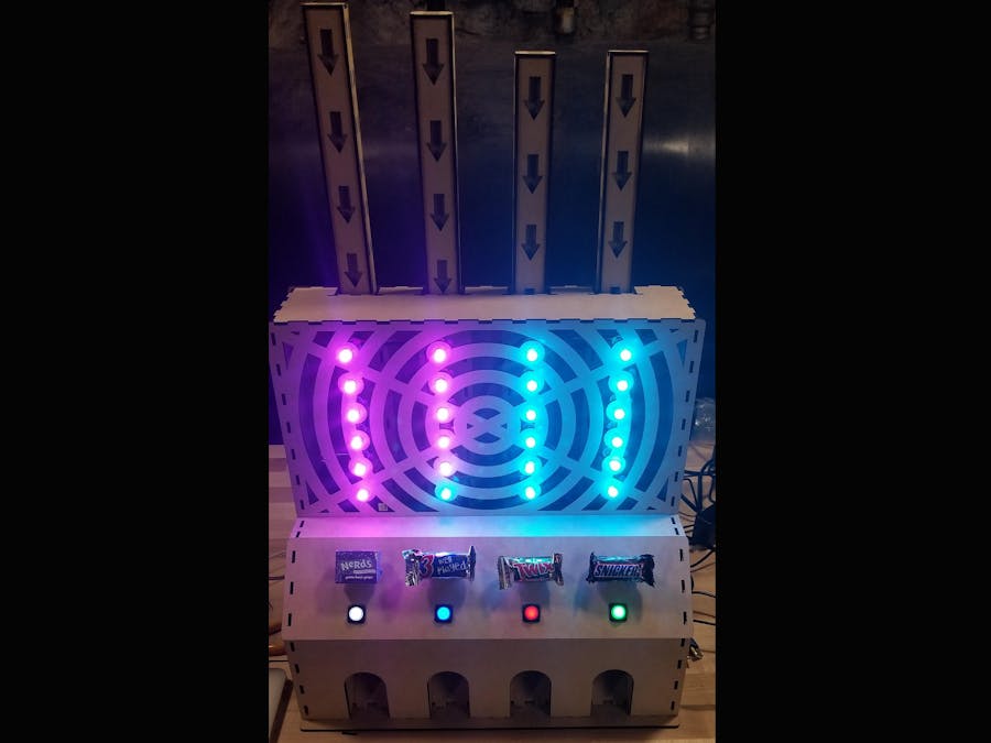
Finally, in 2013 light started shining again. A lot had happened in the last 25 years, including the birth of Arduino and Adafruit (as well as my kids – the new heirs to the Machine). We built V1 which finally lived up to the vision of creating a fully autonomous candy robot. It worked reasonably well, but did jam up (sometimes the candy bars couldn’t turn the corner of the PVC elbow) and would periodically freeze and need to be hard reset when a sugar-fueled trick or treater mashed all the buttons at once. We had a good run with it for 5 years. However, this year, having recently acquired an amazing Glowforge laser cutter and MarkForged carbon fiber 3D printer, we decided it was time for V2 to address some of the issues with V1.
Specifically, we wanted to:
- Make the candy dispensing bulletproof. No more jams or mis-fires.
- Improve the inter-processor communications (we used one processor to run the buttons and stepper motors, and another to run the light show). To get the timing right, they needed to talk to each other and stay in sync.
- Not freeze up when a kid hits every button within 10 ms.
- Build a more robust housing (V1 used the traditional beer box for the outer shell).
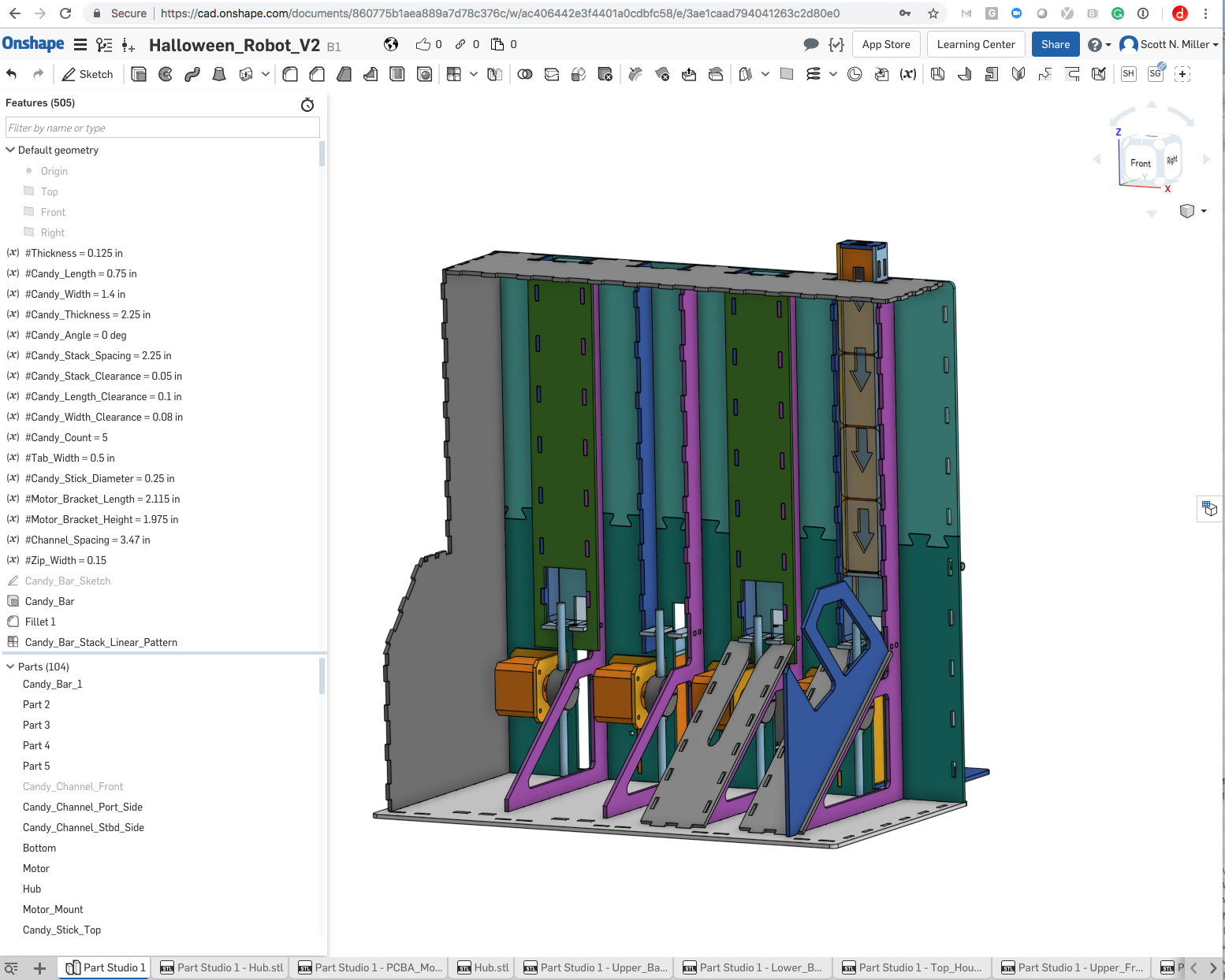
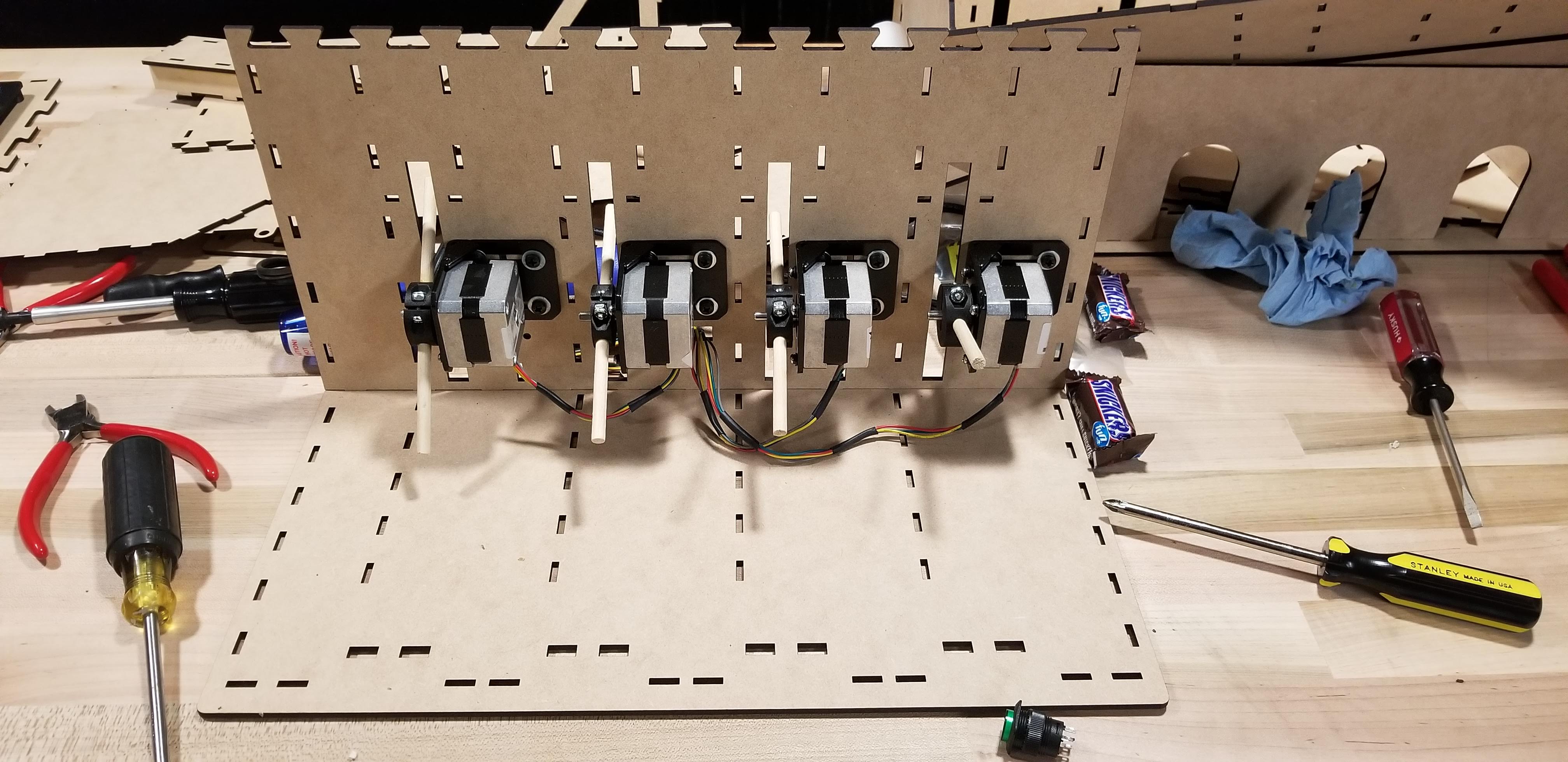
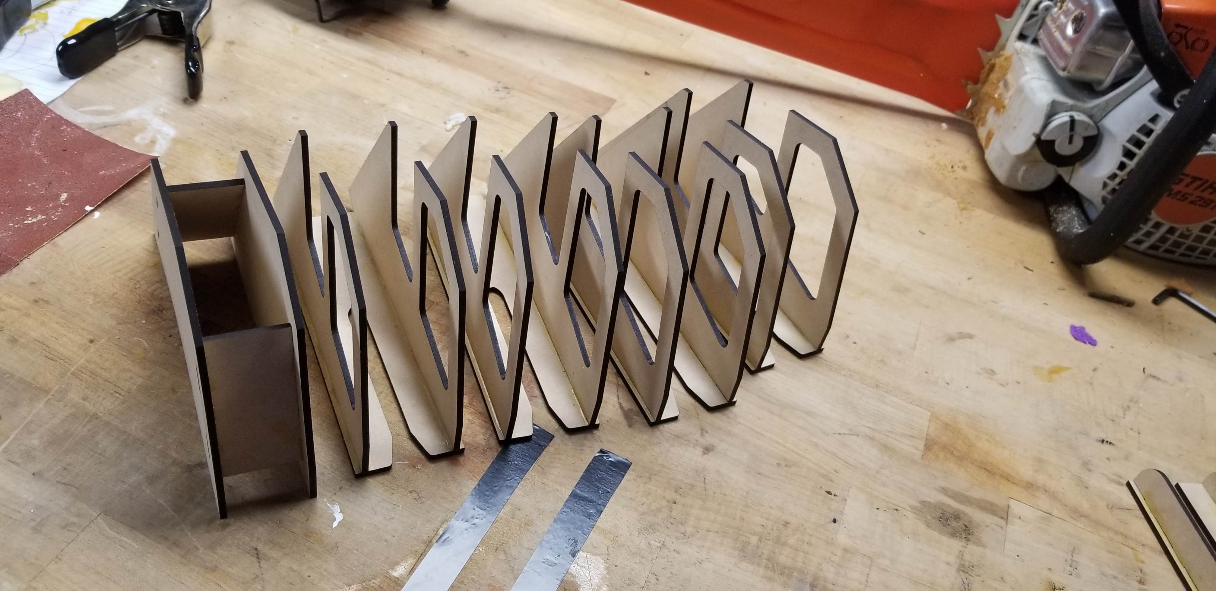
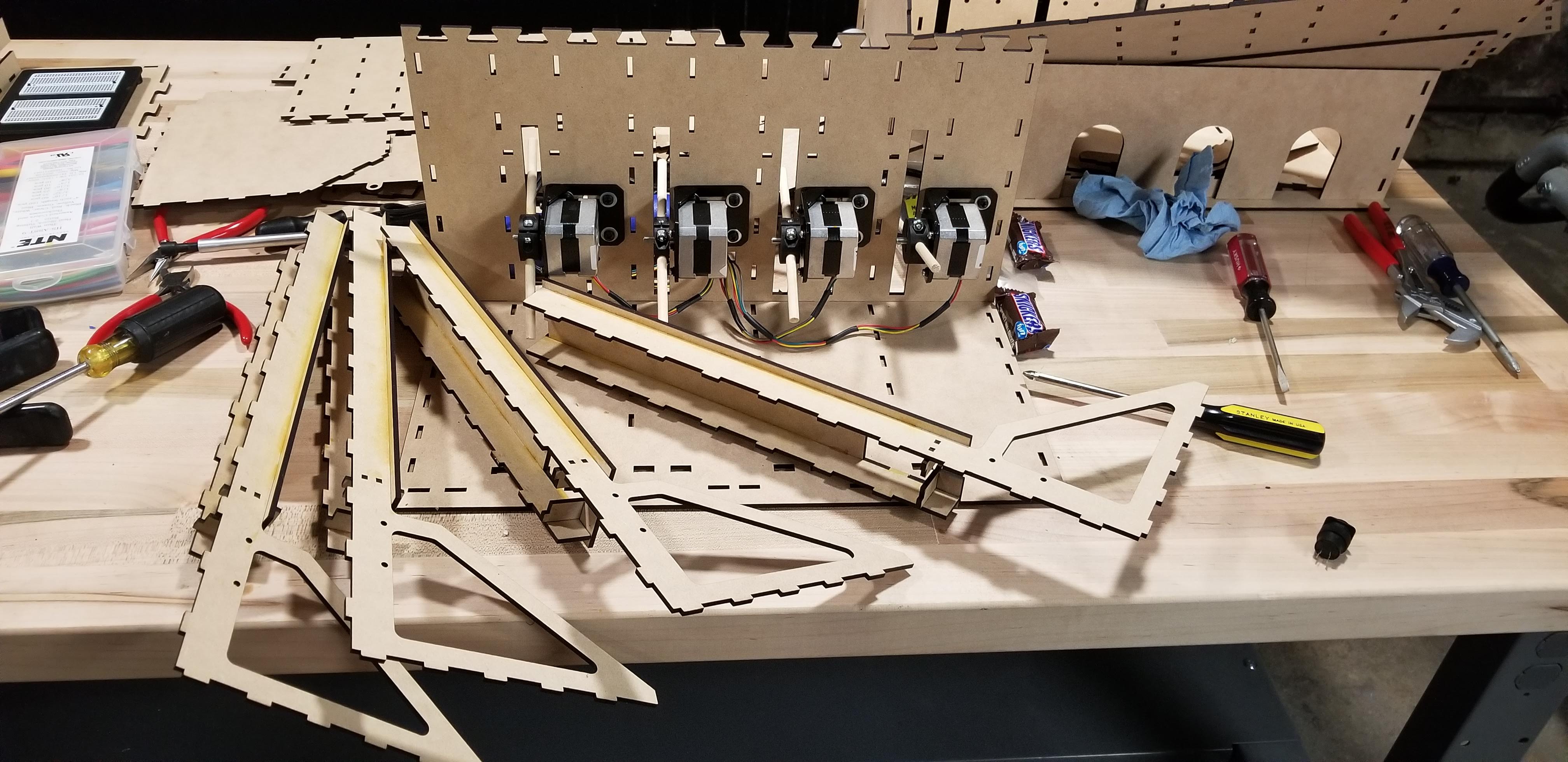
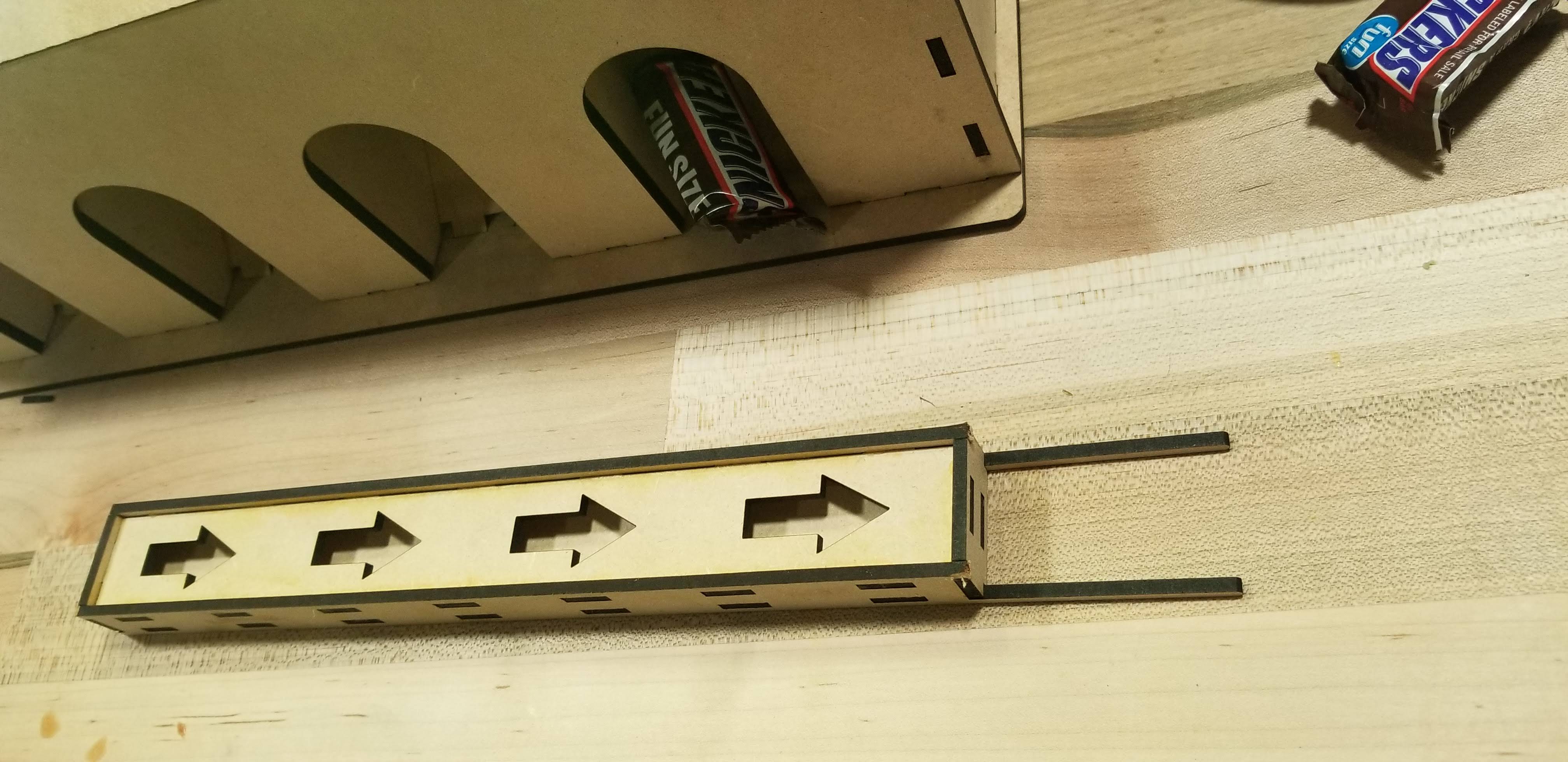
We continued with the stepper motors, as they generate sufficient torque and are indexable. We considered using a merry-go-round or a Ferris whee to hold the candy, but decided to stay with the channel approach for simplicity (the fewer times the candy needs to turn corners, the better). Rather than using PVC tubing, which only comes in fixed IDs, we decided to laser cut custom channels. Initially, we tried stacking the candy bars top to bottom, figuring we could get the highest pack density. However, when loading, the candy would tend to nose dive and jam up, as the bars were not fully constrained. To counter this problem, we tried a version with a slanted bottom shelf, but this didn’t reliably solve the issue. Ultimately, we went back to the end-to-end configuration, as the candy is fully constrained and can only go in one direction (down).
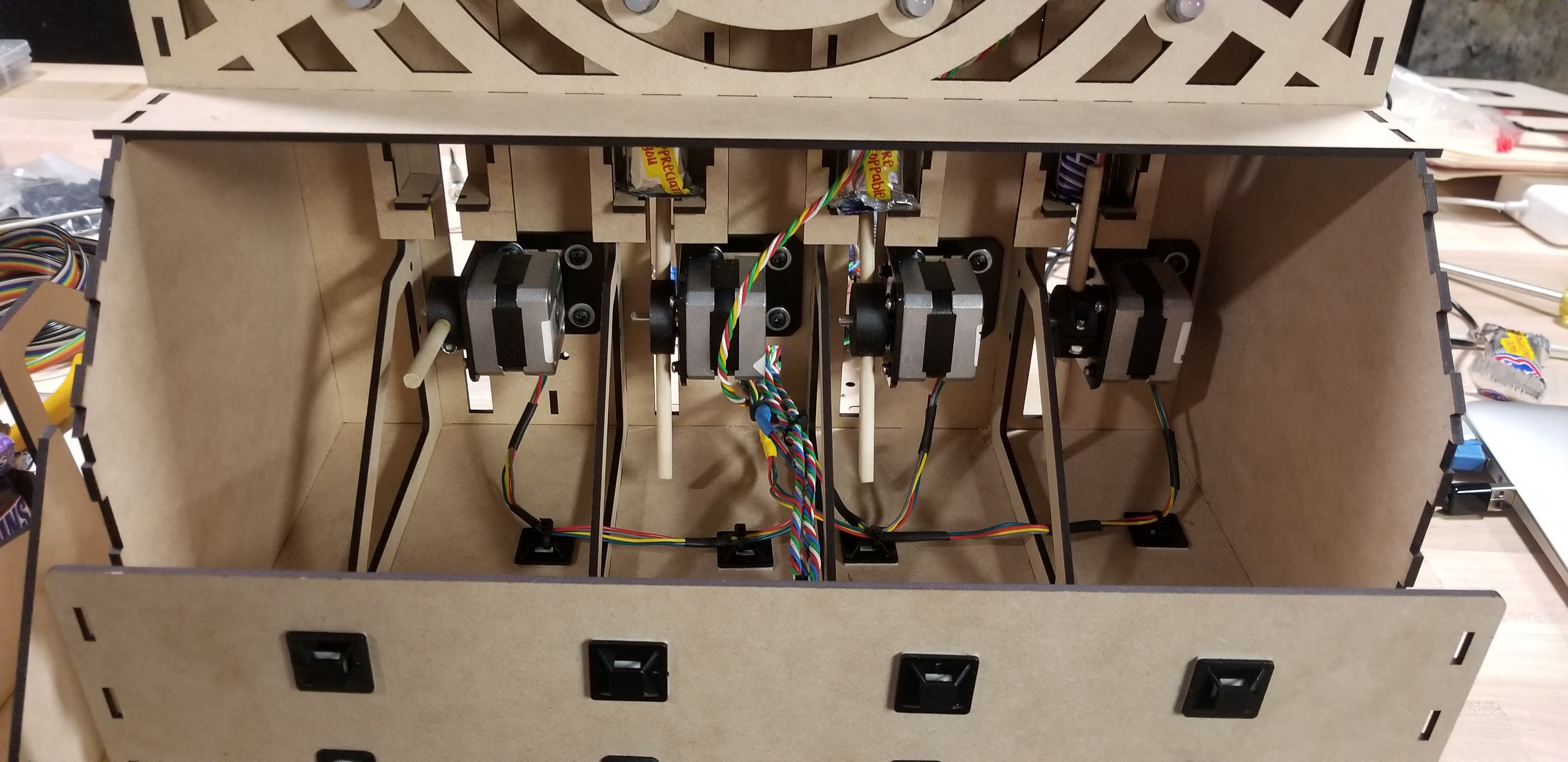
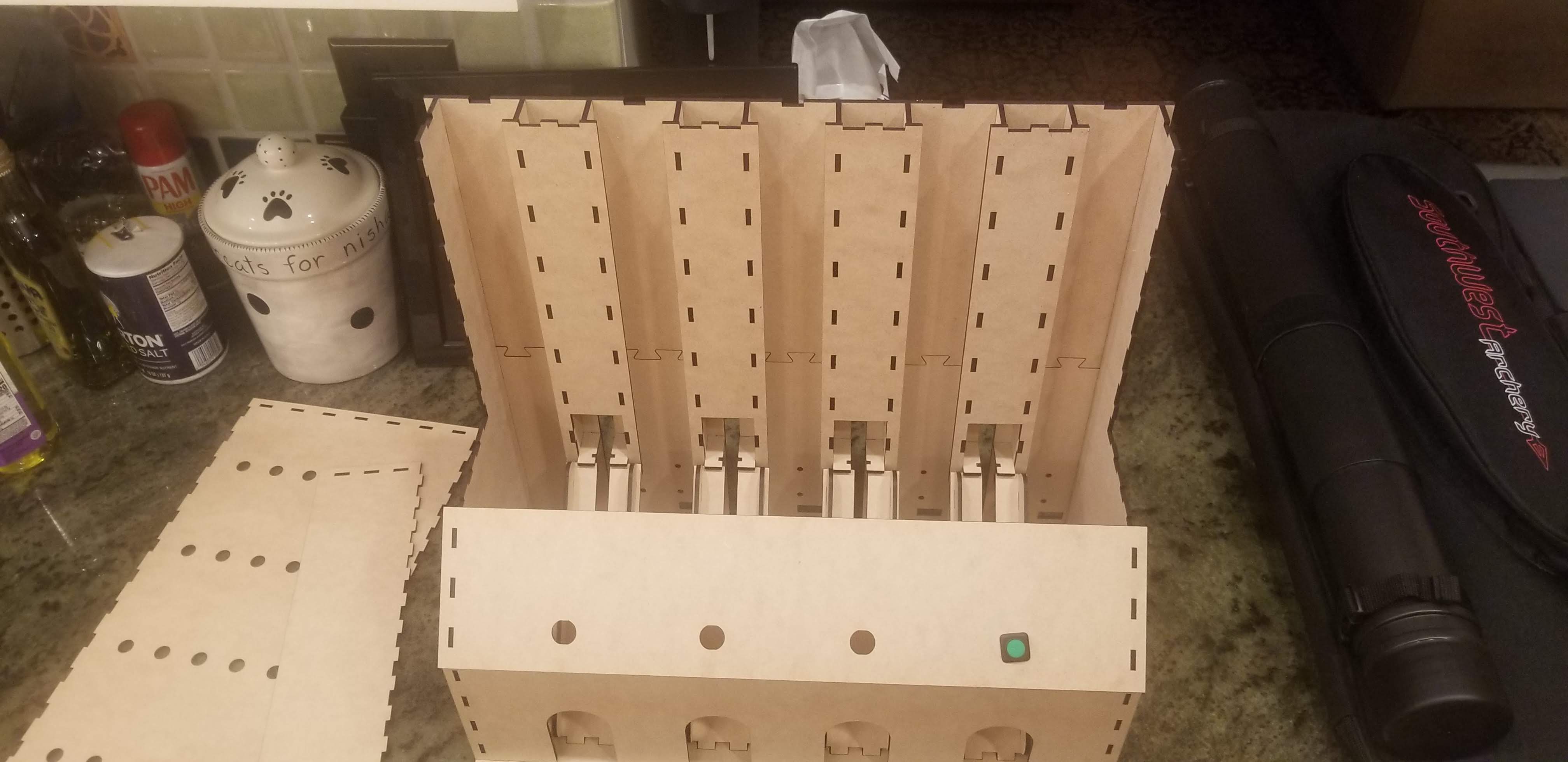
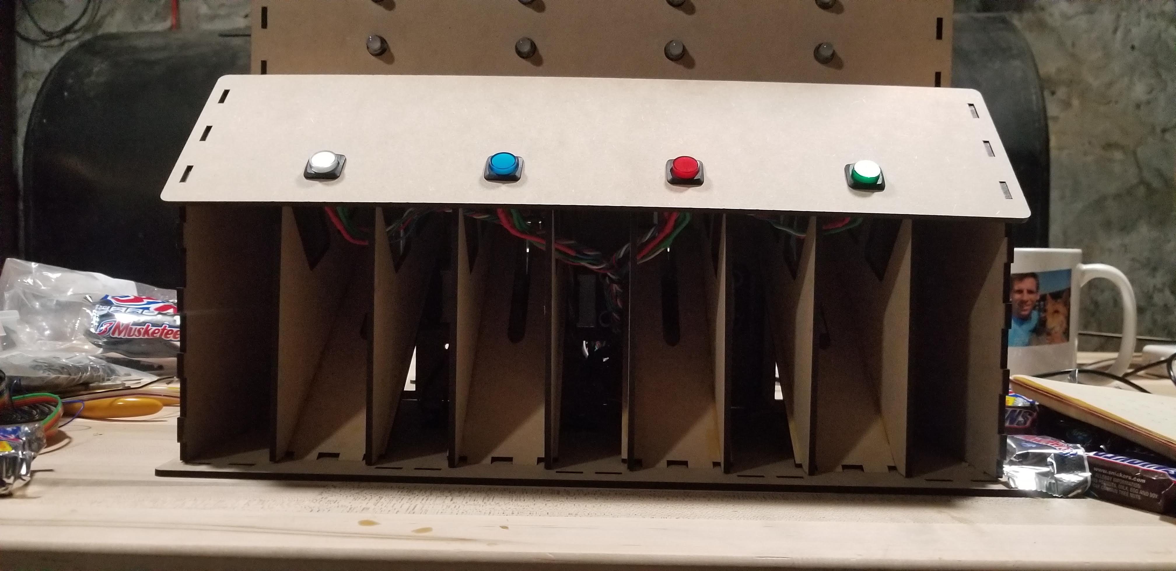
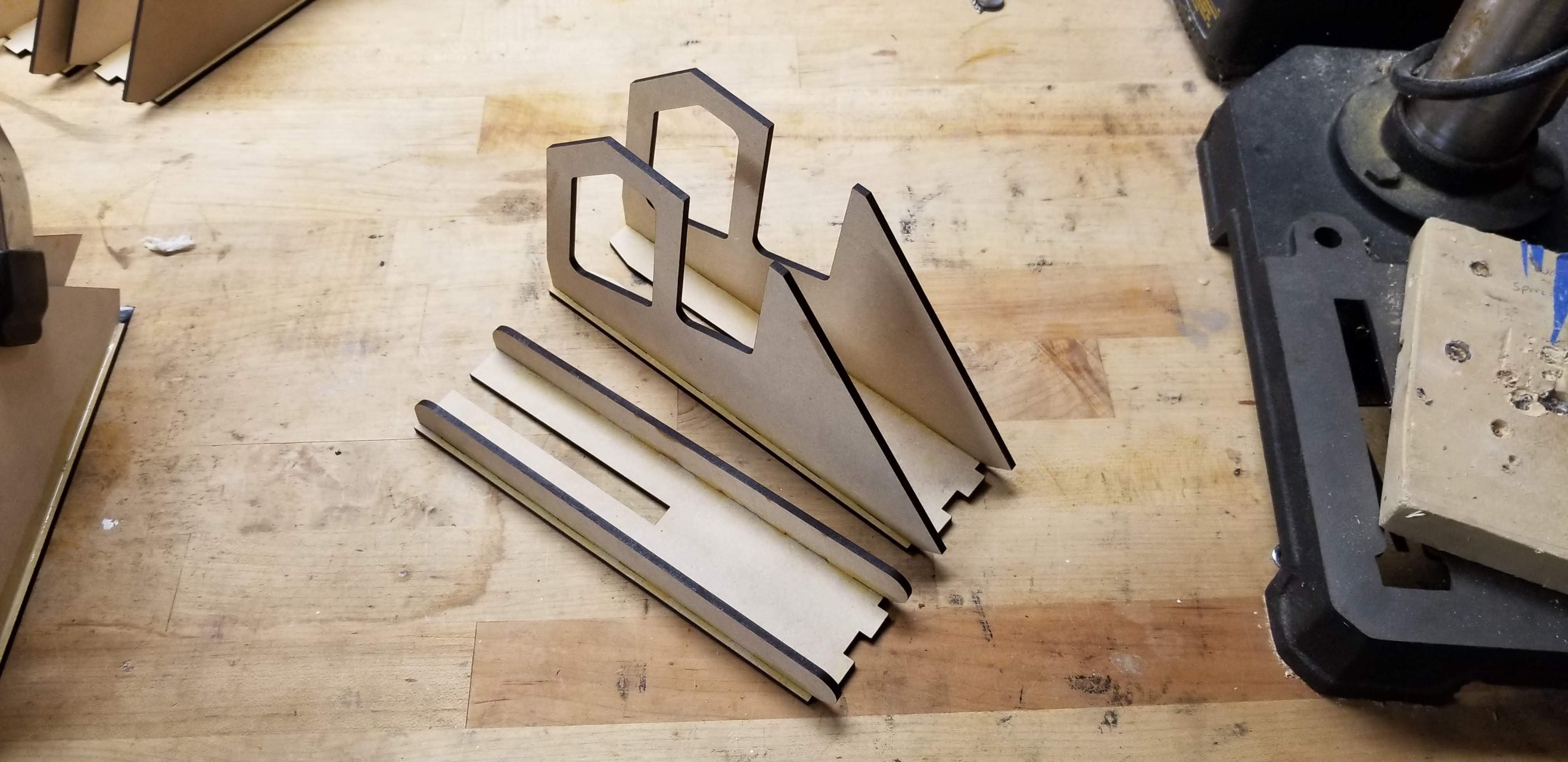
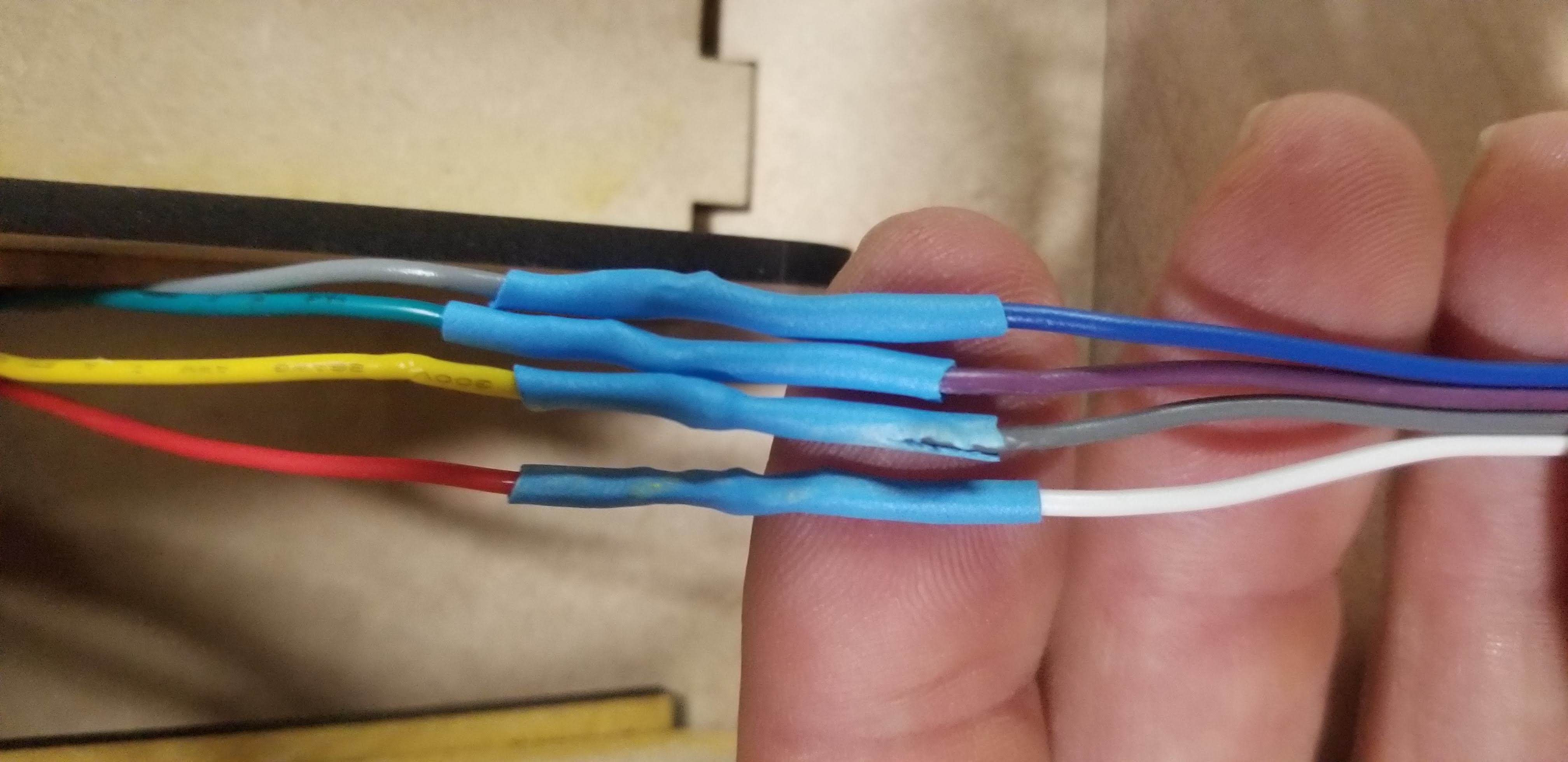
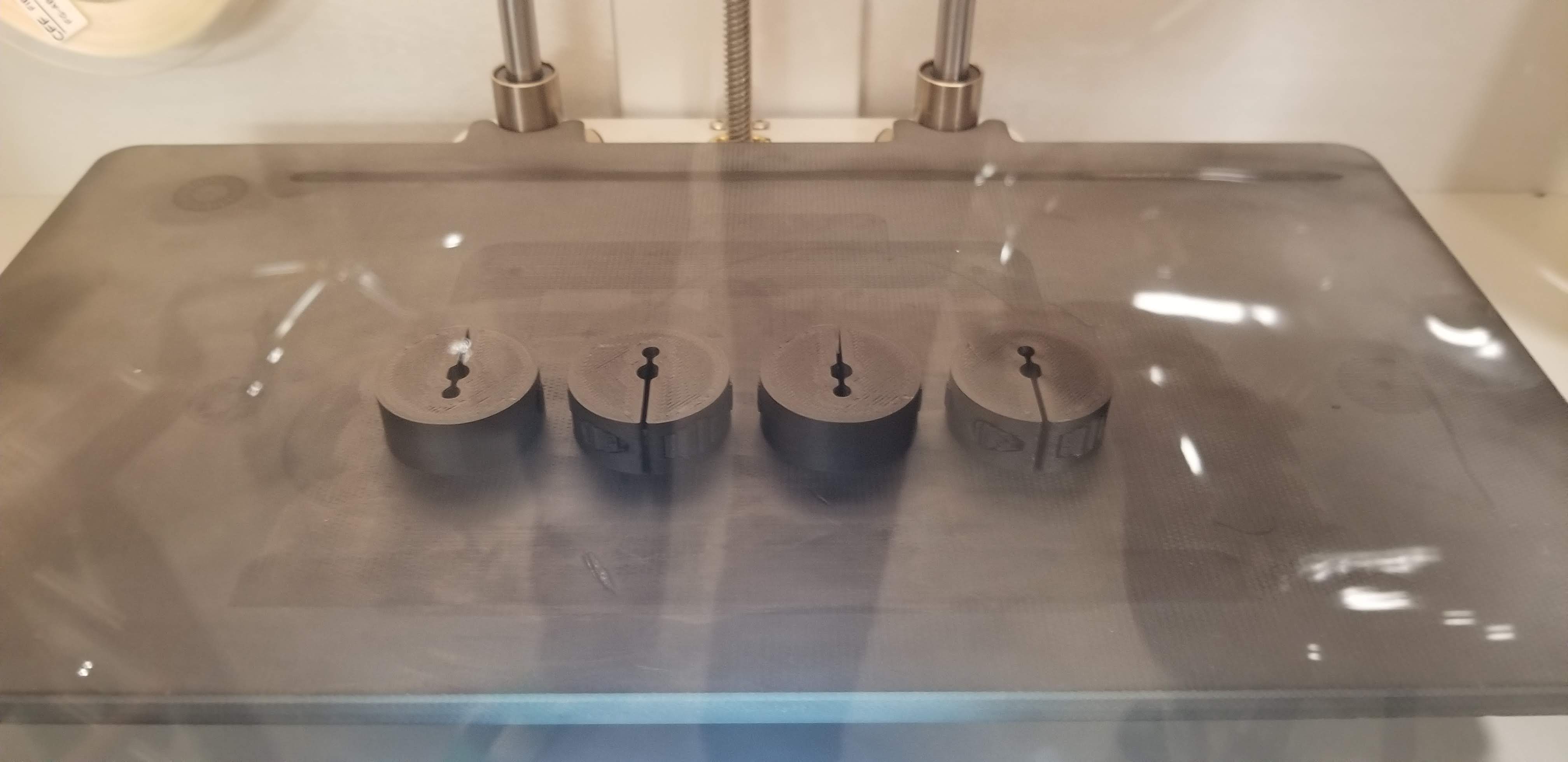
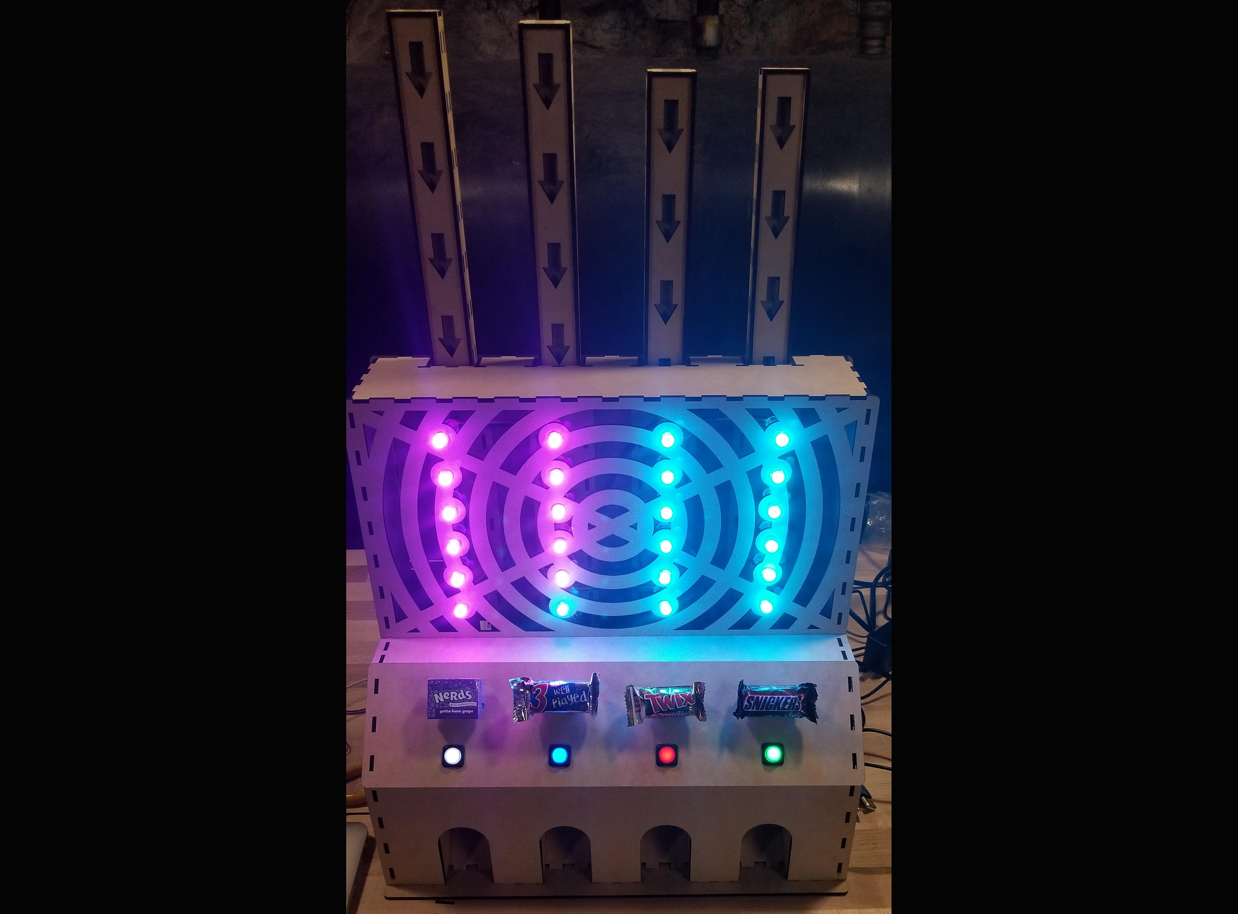
The next task was to figure out the dimensions, as the “Fun Size” has some variation in size bar to bar, as well as the pinched end flaps that extend out beyond the body of the candy. After five or so iterations, we found a channel size that worked well. The candy is loaded in from the top and gravity fed. A pusher stick attached via a hub to the stepper motors acts as a gate until it is activated, preventing accidental discharge. Its mate, 180 degrees around, kicks out the candy out of the channel when activated by the stepper. This system proved to work quite reliably. The main drawback is the lower capacity of candy due to the end-to-end stacking. The pusher sticks also needed clearance to spin, so it was necessary to make sure they didn’t catch the wiring harnesses in their arc.
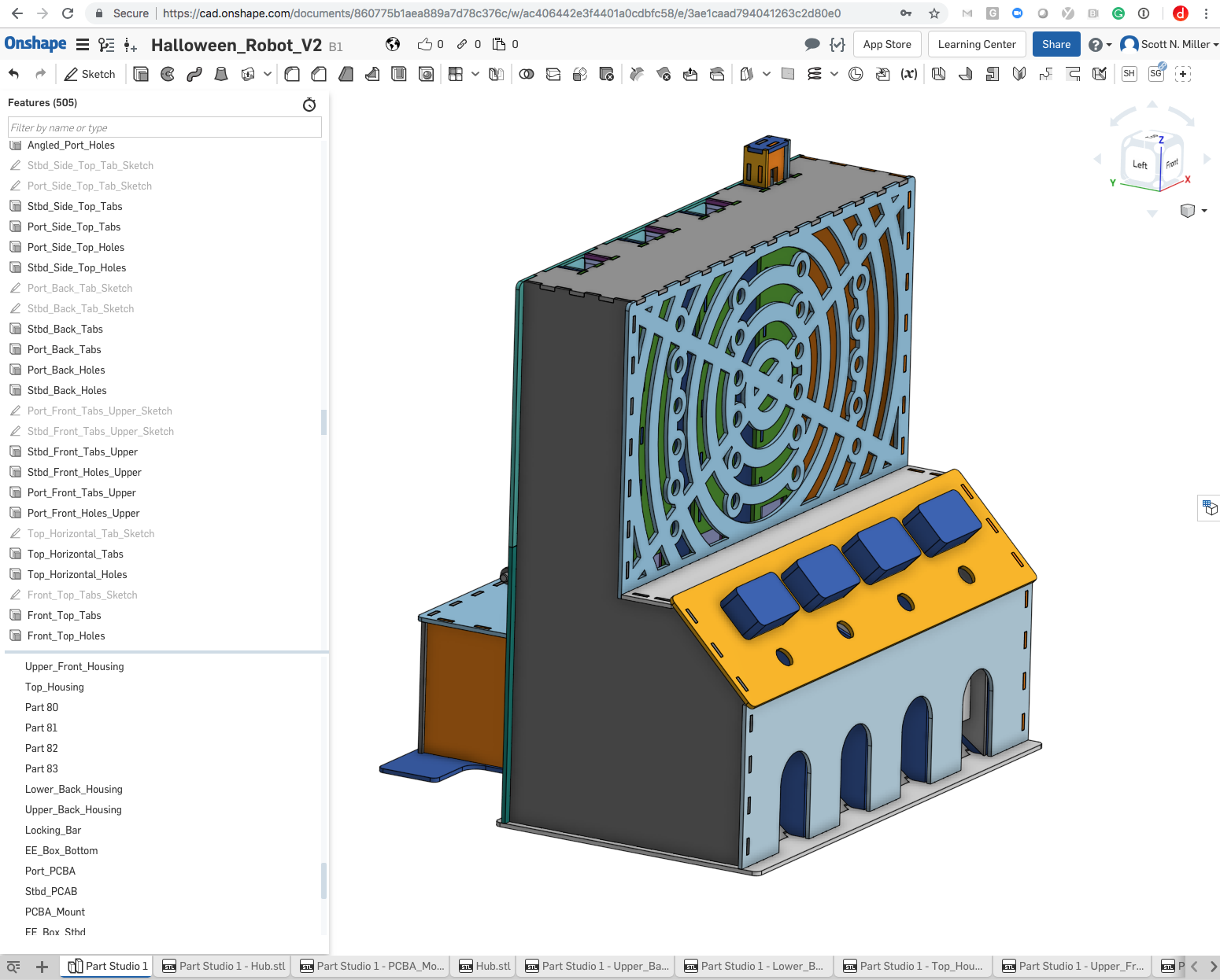
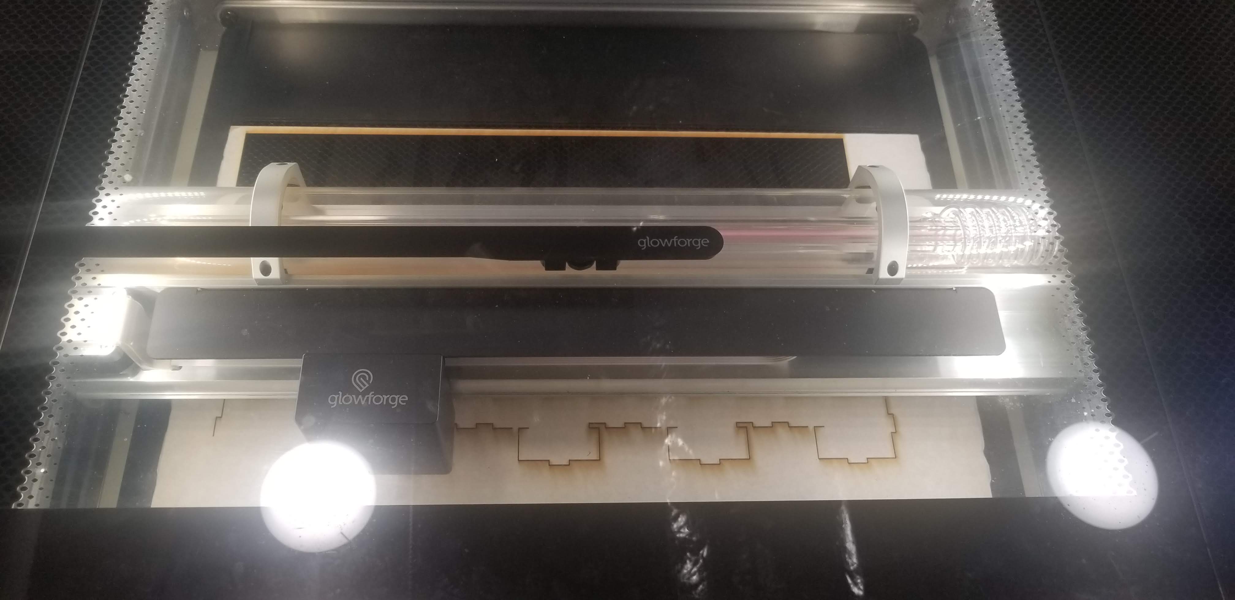
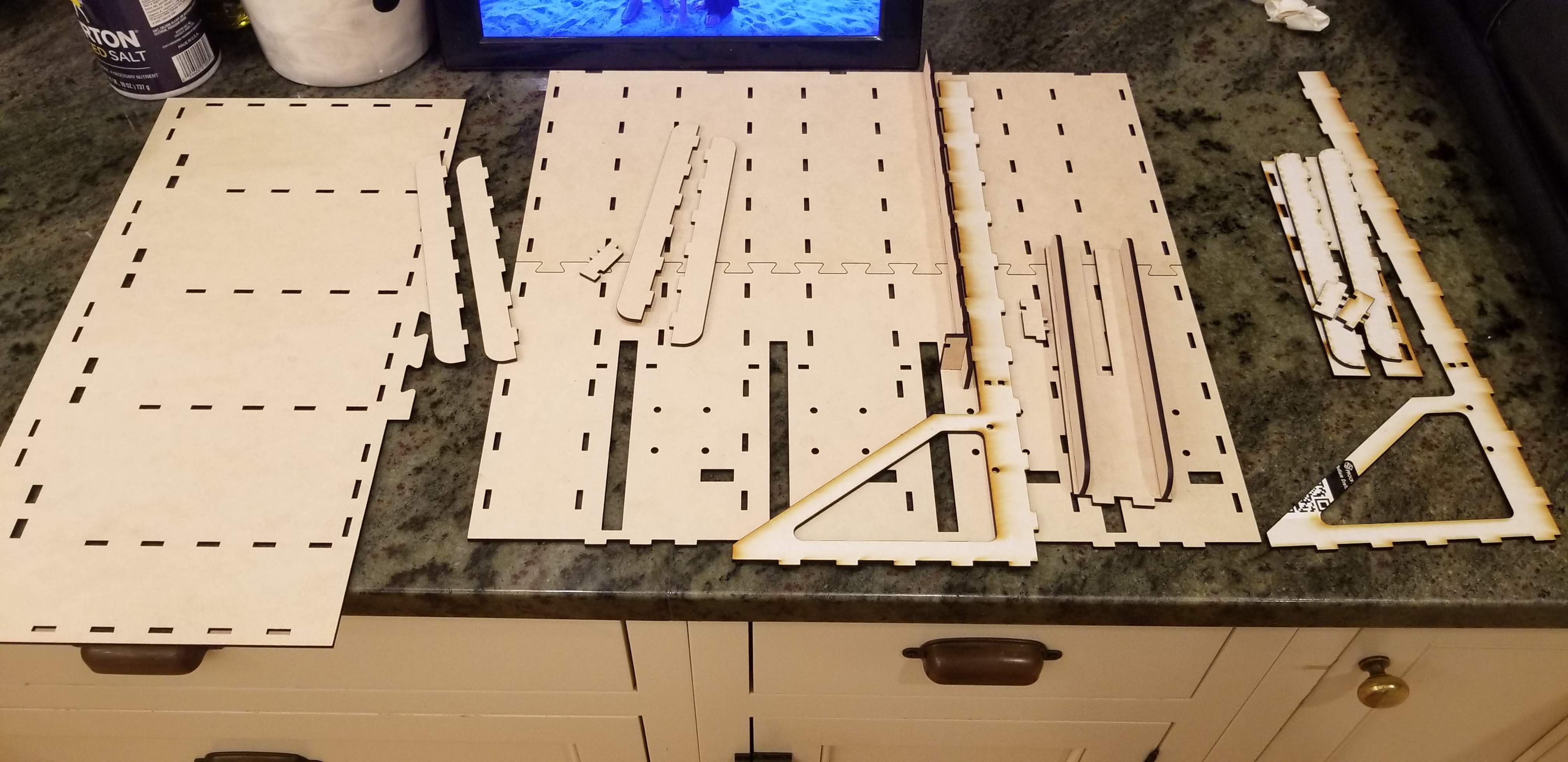
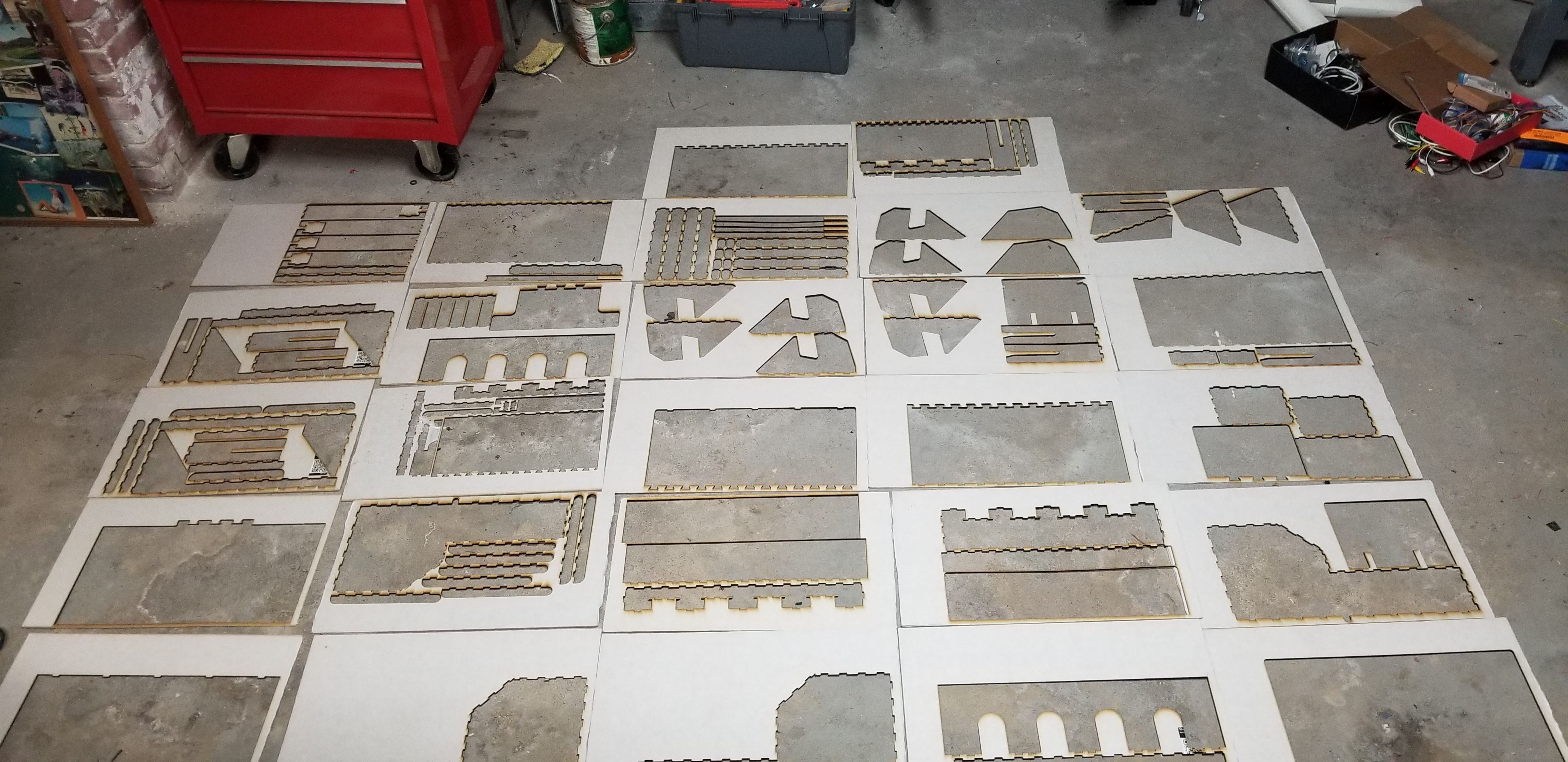
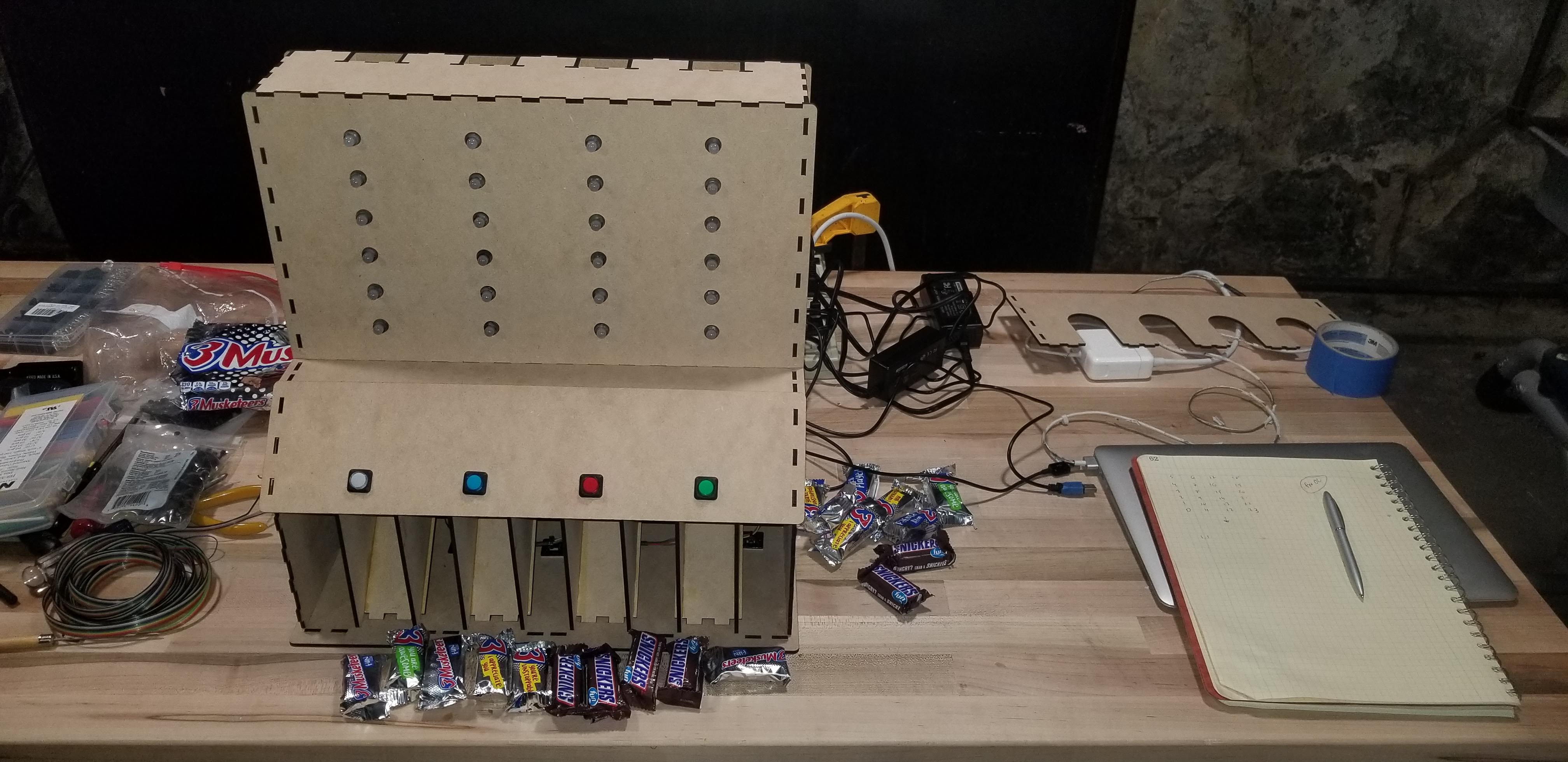
HousingNow that we had locked down the candy dispensing, we patterned this in Onshape and then built the outer housing around it. Because we were using a Glowforge laser cutter (which is great because of the large bed size and quick cut times), we used a tab and slot design to attached the various components. We tried to be thoughtful about how the parts would be assembled and self-locking, and also to include modularity and accessibility. In a few cases, the parts were too big, so we split them up and used a dovetail to attach them. My daughter had some great advice on the Back piece for how to maintain the structural integrity by running the cut perpendicular to the candy channels. Due to the kerf of the laser, we didn’t need to leave clearance for the tabs.
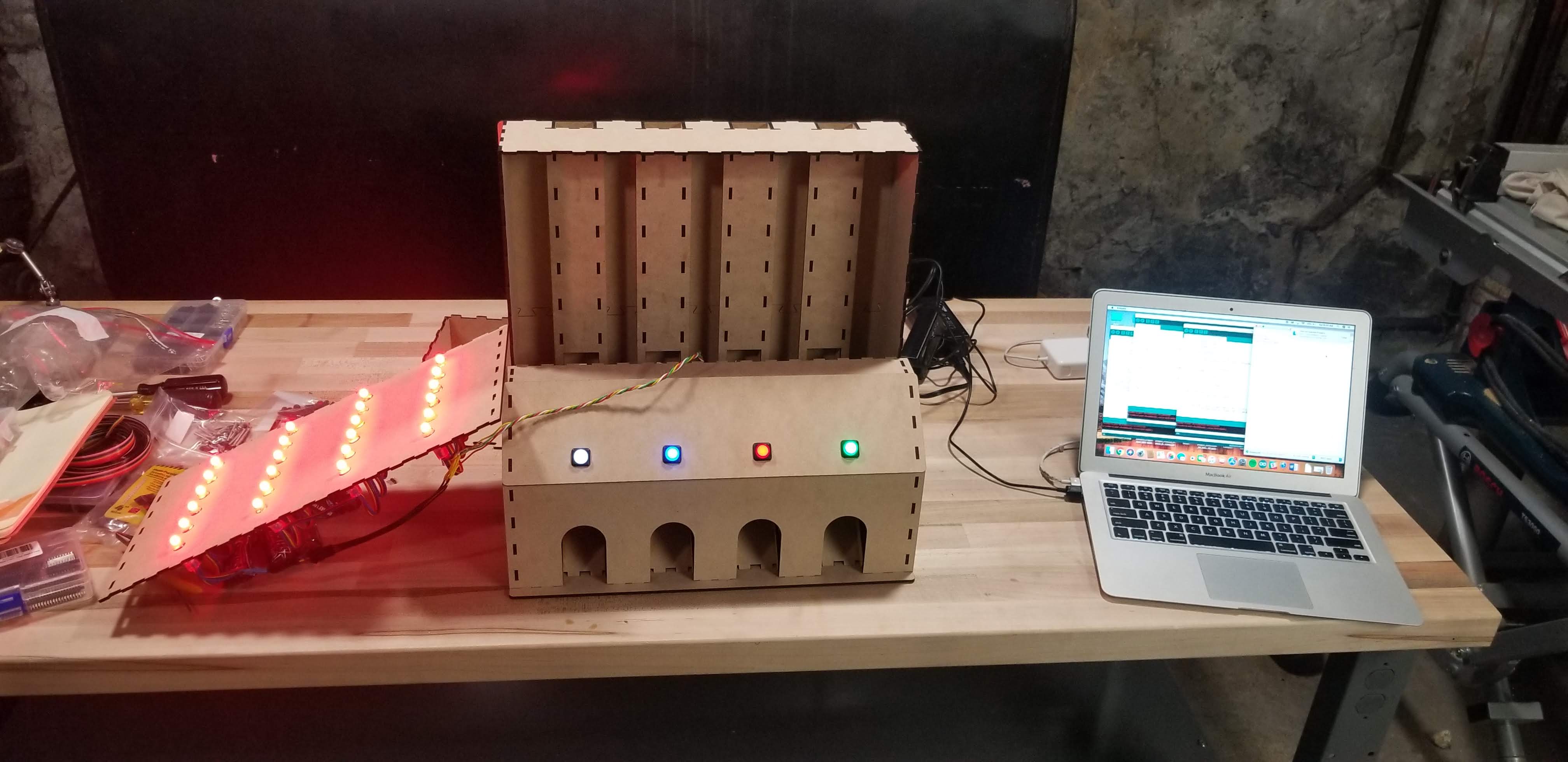
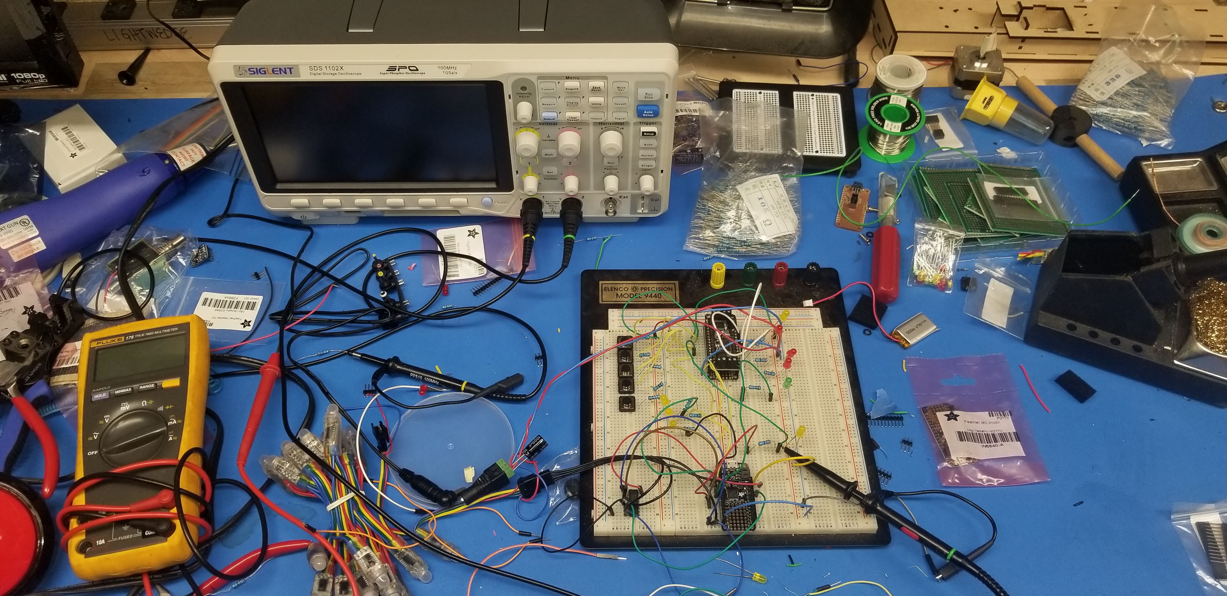
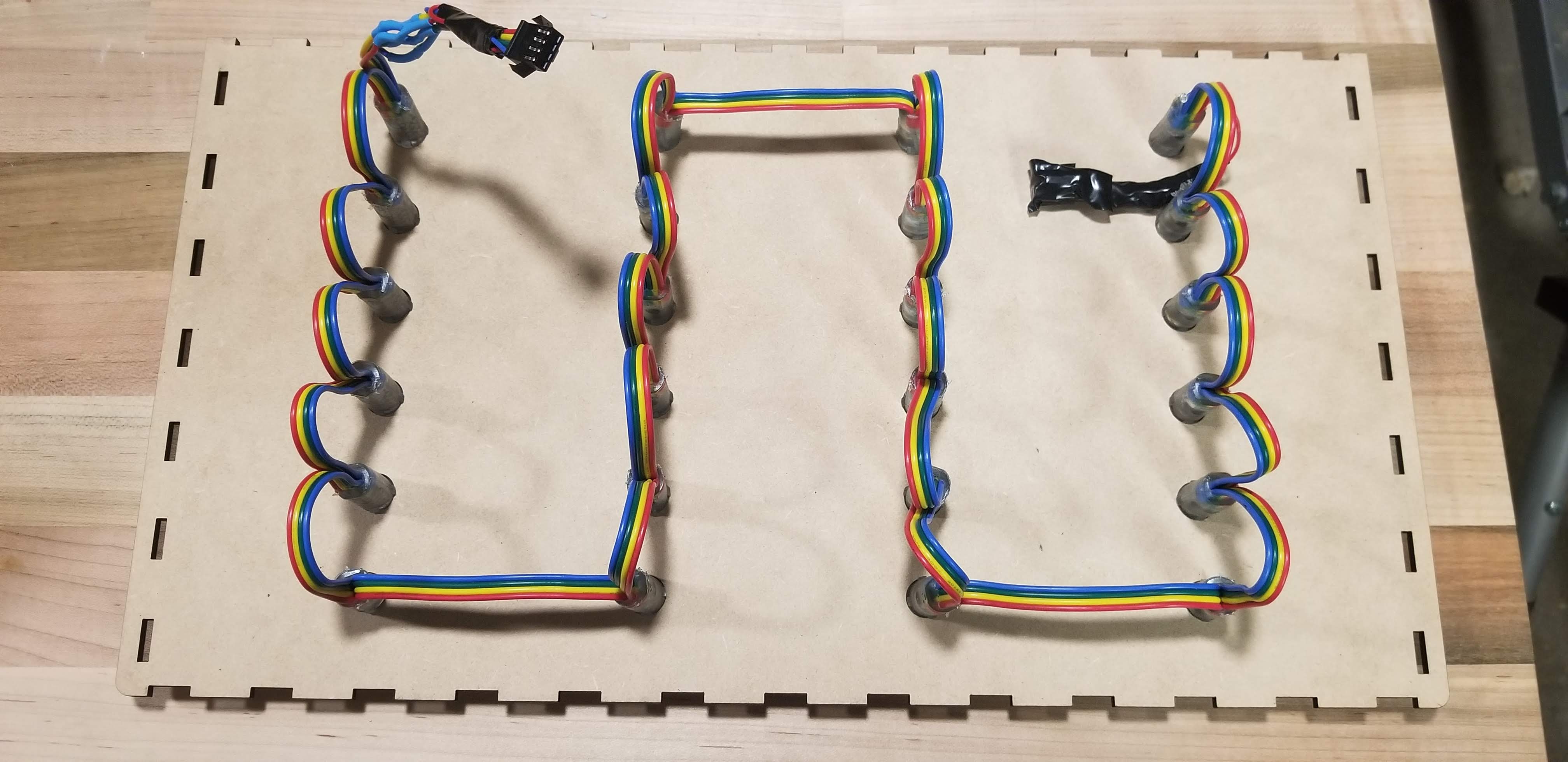
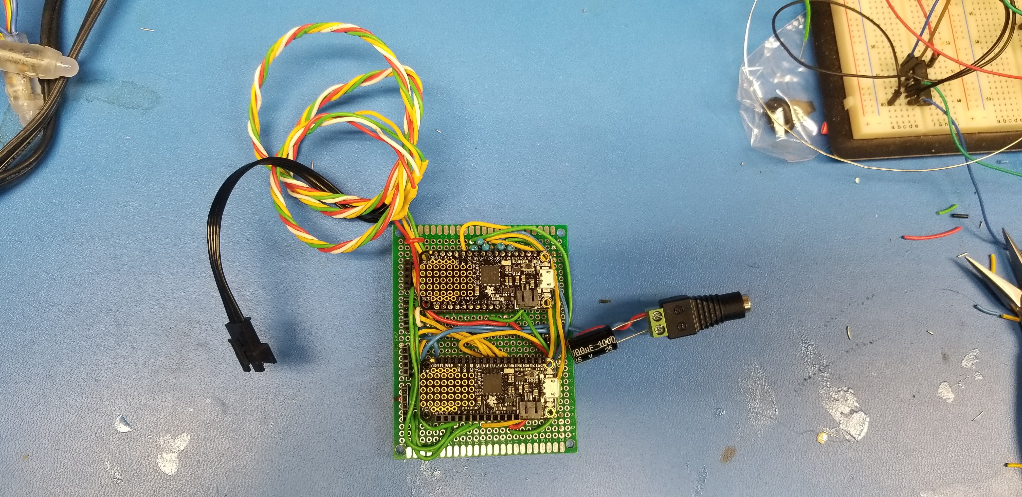
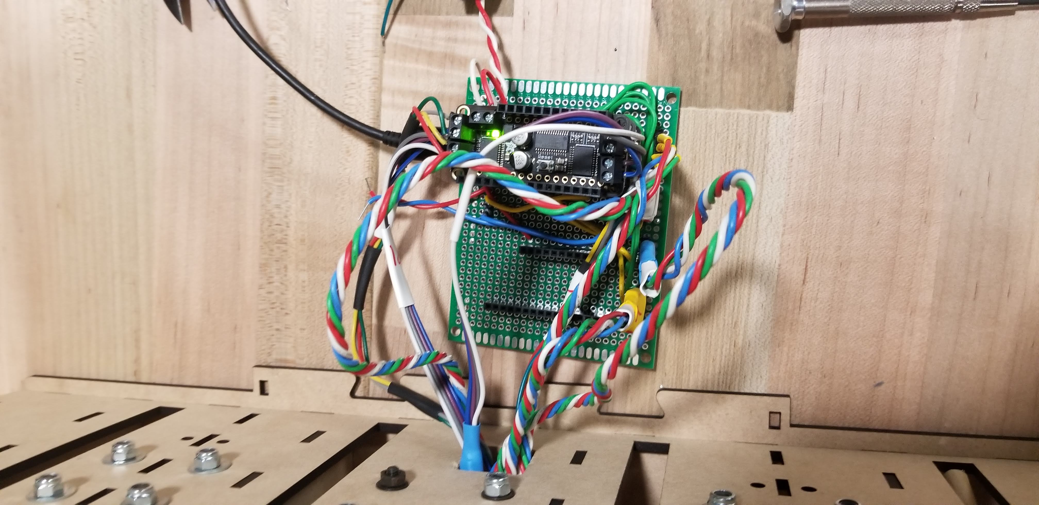
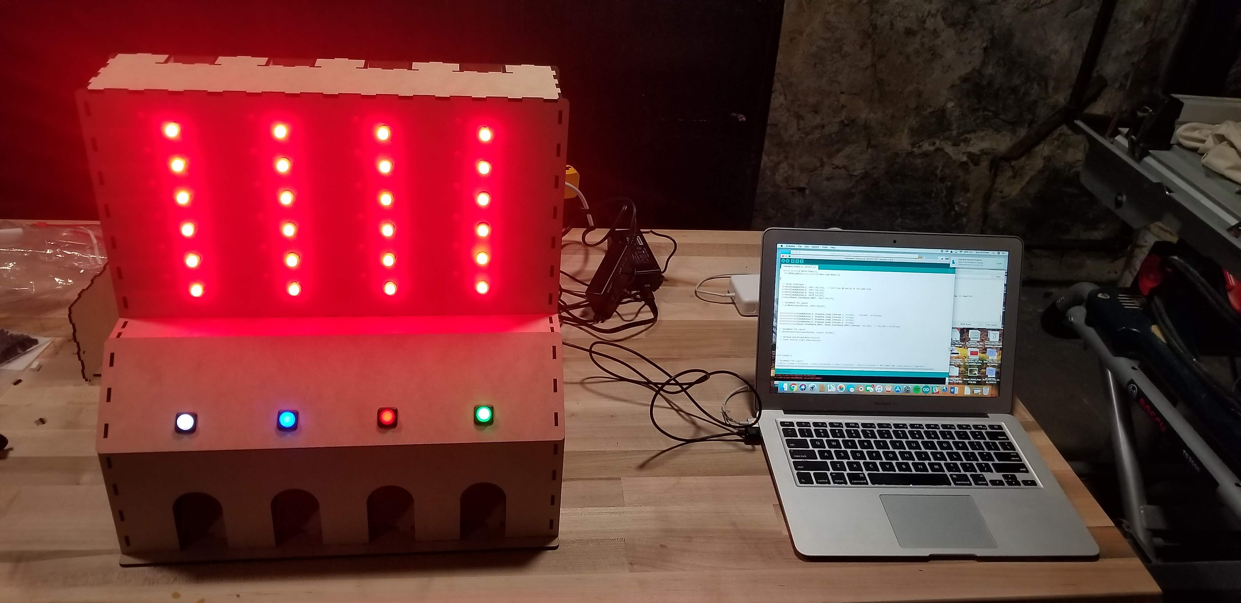
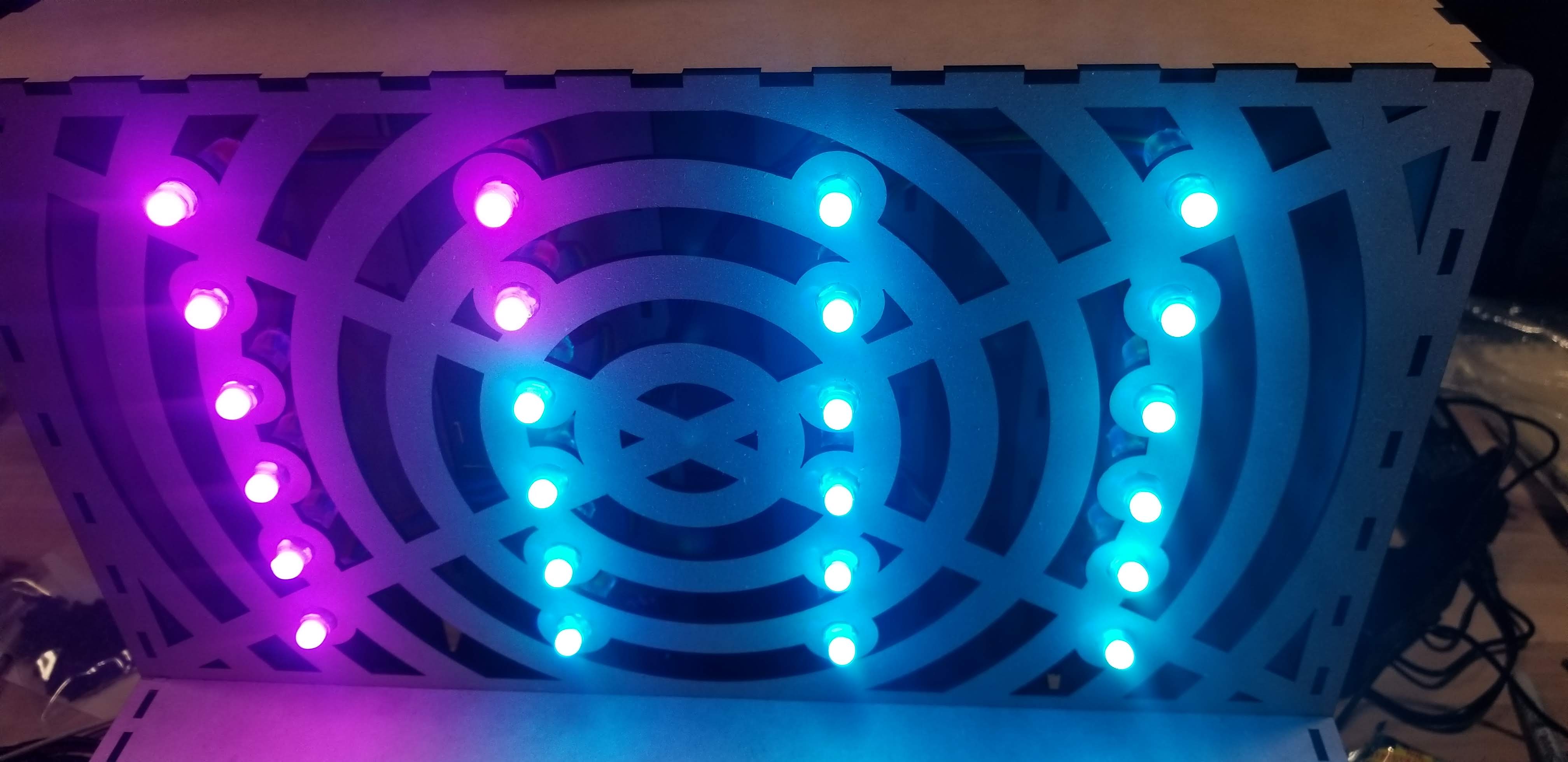
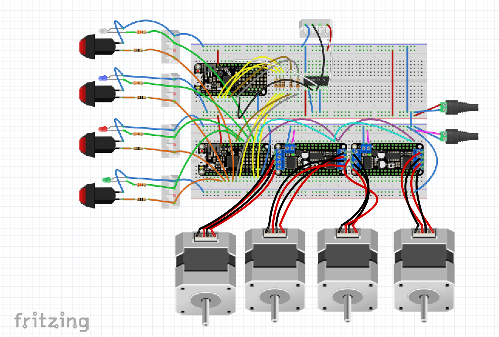
ElectricalAs noted, we stayed with a dual processor design, selecting the Adafruit Feather M0 Basic Proto - ATSAMD21 Cortex M0 with stepper shields. These processors proved to be incredibly easy to talk to and well supported. The dual processor design added some complexity in having the processors communicate with each other to stay in sync, but provided for future accessories (such as a catapult) with the extra i/o. The processors communicated data on three lines providing eight states and then used an interrupt triggers in each direction (5 wires total) For the light show, we used the Adafruit RGB Pixel Strand which was snaked into a matrix. An external 74AHCT125 - Quad Level-Shifter (3V to 5V) chip was needed to bump up voltage chip from the 3.3v coming out of the Feather to 5 Volts going into the LED string.
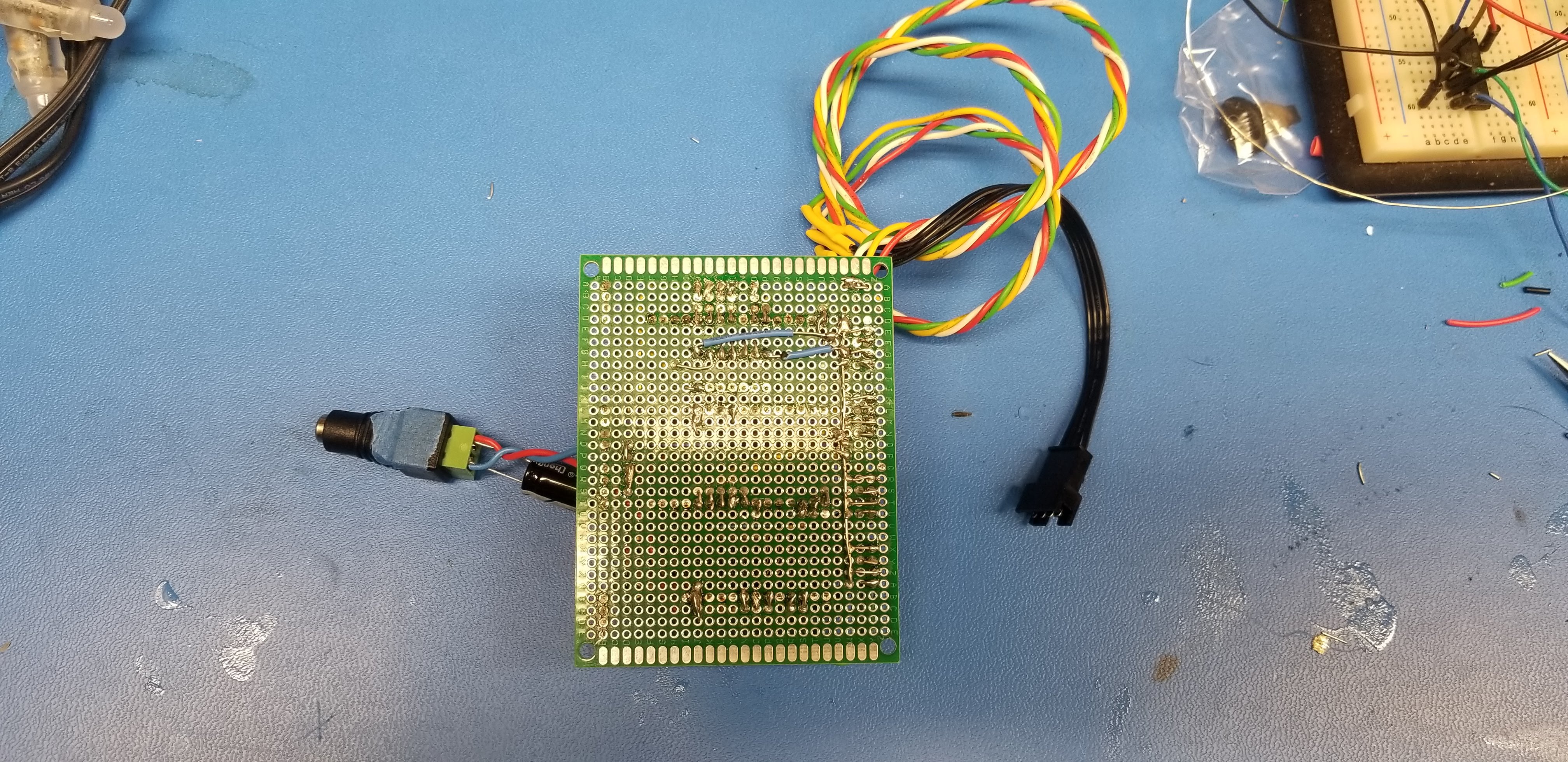
We used a breadboard to test out the wiring and then soldered up a protoboard with sockets for the two processors (in case we fried the processors inadvertently). The voltage level shifter is tucked under the light processor, as we were running out of space on the board. Connectors make it easy to remove the main unit.
SoftwareTo improve the responsiveness of reacting to button presses and minimize the chance of freezing up when multiple buttons are pressed simultaneously, we decided on a hardware interrupt driven approach. When released, the button triggers a HW interrupt that activates a SW flag indicating which button was pressed. We kept the interrupt function to one line of code to handle the case where the button is pressed multiple times and used a flag that would activate a separate function dispensing the candy. The main loop is also kept short it improve responsiveness.
For the light show, we remapped LED string from a linear series into a matrix (rows / columns), and then created multiple animations for both when the robot was idle and when a button was pressed.
ObservationsOverall, V2 worked quite well, and I’m proud we accomplished our goals. We noticed some dimensional variation in the Fun Size bars – it seems they are a bit thicker this year. While the design of V1 was not as robust, from an ID standpoint, I think it was a bit more playful and something a mad scientist would build. It also did a nice job of exposing the inner workings, which is fun to see. It was great for the kids to get involved with the mechanical design in Onshape, laser cutting on Glowforge, and programming the colors on the Adafruit Feather. It made what seemed mysterious (how do those machines work) much more understandable and approachable.
What’s Next- Now that we’ve got the basic Machine working well, there are many new features we can add for next year, including:
- Adjustable candy channels to handle future variations in the Fun size.
- Ability to handle different candies such as lollypops and Twizzlers.
- More lights.
- Sounds!
- A catapult to collect the candy and then “Tom Brady” it to the trick-or-treater’s bag.






Comments
Please log in or sign up to comment.