


Hardware components | ||||||
 |
| × | 1 | |||
 |
| × | 1 | |||
| × | 1 | ||||
| × | 1 | ||||
| × | 1 | ||||
Software apps and online services | ||||||
 |
| |||||
Hi folks,
i had the idea to import my gadgeteer modules to let them work with the raspberry pi 2 and Windows 10 IoT Core. I want to start here with the led7r module from GHI Electronics.
Ok... firstly i thinked... Hey that is easy. i put only the pins to free gpio pins and thats it... But then you used a lot of the gpio pins from the raspberry pi 2 and then i decided me to choose a way over I2C.
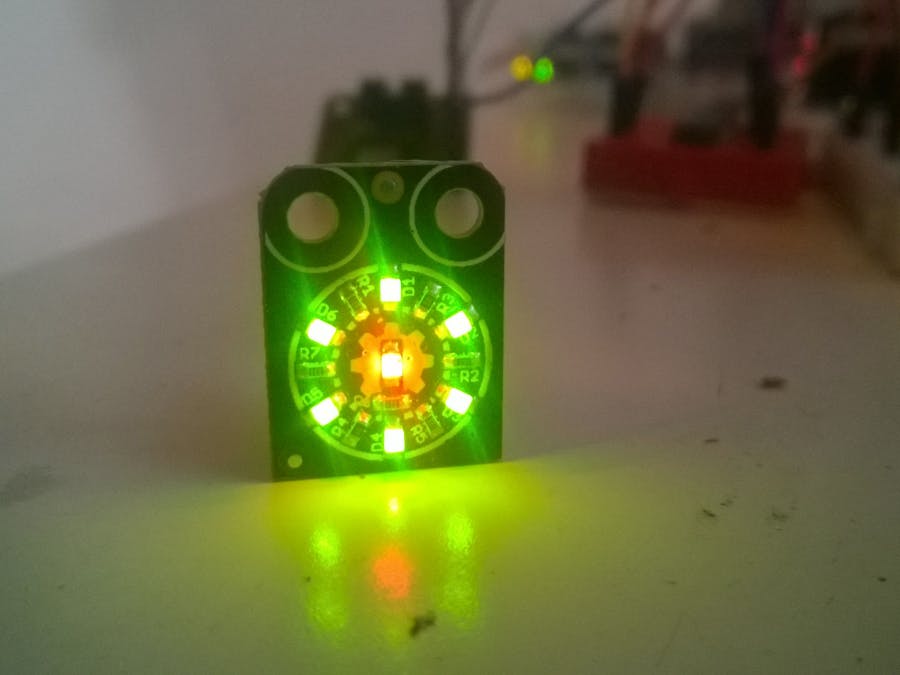
A small info about the LED7R Modul:
The LED7R Modul has 6 green and one red leds. Every led has a 330 Ohm resistor. Its typical for the ghi modules to speak with a specific board (like the FEZ Spider II) over a 10 pole wire. One pole for 3,3V, one for 5,5V, one for GND and 7 bidirectional I/0 pins. Its a great architecture for the gadgeteer technologie. Simple plug&play... Great! But if you want to use the module in other projects its not so comfortable. For this problem GHI had made a module... the expander module. With this module its easier to connect the pins from the modules
To connect all the gpio pins from the expander module over I2C we use the MCP23017 16 Bit I/O Expander. Sure you can use a smaller I/O Expander but this is the chip that i had found at home.
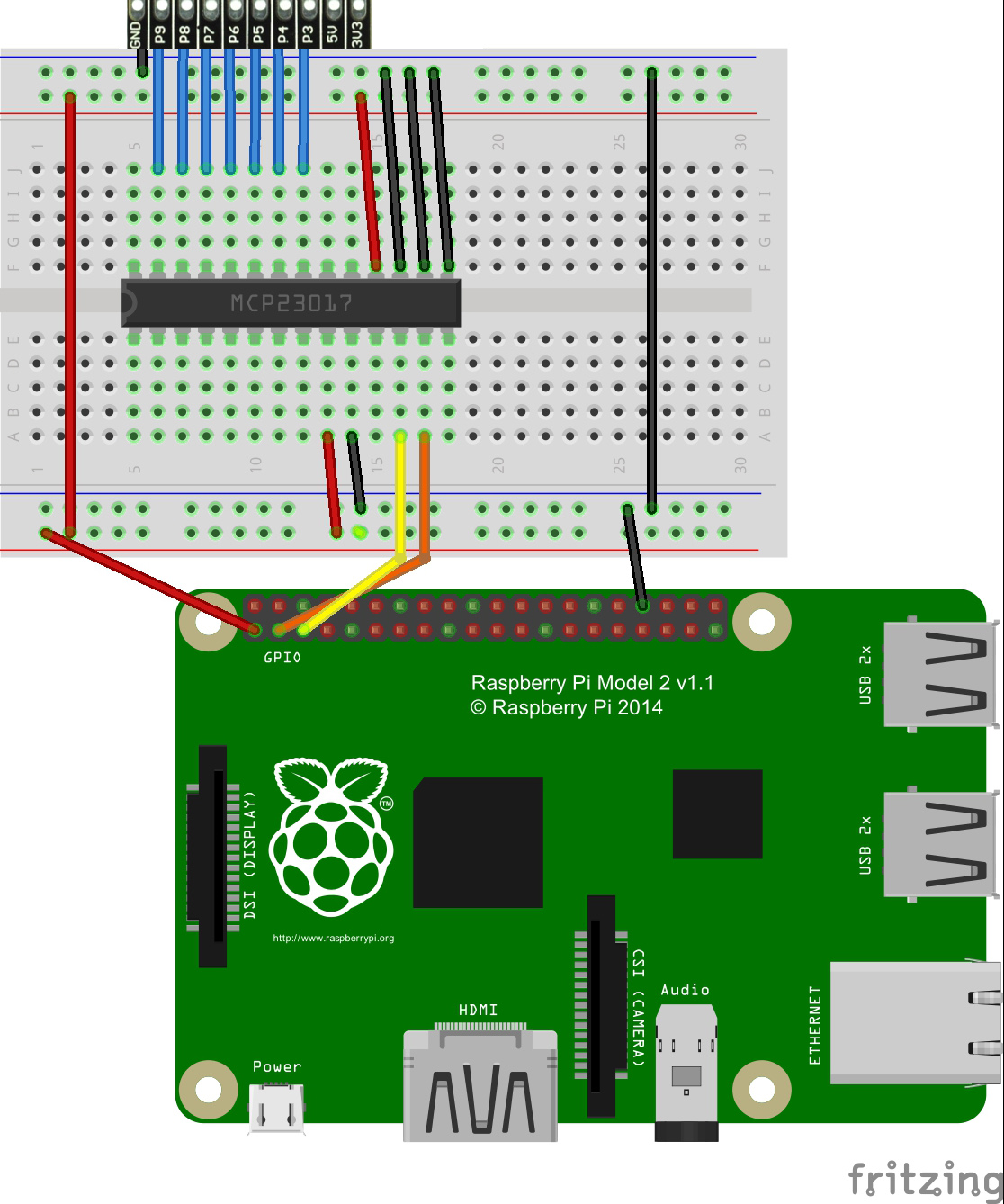
Part 1: Connections
On the fritzing picture you can see how to wire the connections.
MCP23017
To understand the MCP23017 i would recommend to reed the datasheet. i know the normal software engineer like me dont like the sheets :)
- Pin 12 SCL-> Pin 5 RPI2
- Pin 13 SDA-> Pin 3 RPI2
- Pin 9 VDD-> Breadboard Power Bus
- Pin 10 VSS-> Breadboard Ground Bus
- Pin 15 A0-> Breadboard Ground Bus
- Pin 16 A1-> Breadboard Ground Bus
- Pin 17 A2-> Breadboard Ground Bus
- Pin 18 RESET-> Breadboard Power Bus
- Pin 21 GPA0-> P3 GHI Extender Modul
- Pin 22 GPA1-> P4 GHI Extender Modul
- Pin 23 GPA2-> P5 GHI Extender Modul
- Pin 24 GPA3-> P6 GHI Extender Modul
- Pin 25 GPA4-> P7 GHI Extender Modul
- Pin 26 GPA5-> P8 GHI Extender Modul
- Pin 27 GPA6-> P9 GHI Extender Modul
GHI Extender Modul
- GND-> Breadboard Ground Bus
Raspberry Pi 2
- Pin 1 (3,3V) -> Breadboard Power Bus
- Pin 34 -> Breadboard Ground Bus
Part 2: The theory
After reading the MCP23017 datasheet i came to this results:
The MCP23017 has 2 bus rows (GPA and GPB). Every bus have 8 bidirectional I/O pins. We need to control 7 leds so we only need one bus. I decided me to choose bus A. Now we need to know the right bits to communicate with the 7 leds.
In the following list i had wrote the standard conditions for each led:
If you want to combine some leds, you need to add the bits for the choosen led.
For a better understanding here are two examples:
Example 1:
If we want to turn led 1 and led 2 on.. it would like look like that:
Binary: 0 0 0 0 0 0 1 1
Hey: 0x03
The last bit is for led 1 and the bit next to the last one is for led 2.
Example 2:
If you want to turn all leds on it would like look that:
Binary: 0 1 1 1 1 1 1 1
Hex: 0x7F
Part 3: The Code
After we finish to wire all the pins with the raspberry pi 2 we can start to code :)
I use for my code a UWP class library to use it like a driver for further projects.
Dont forget to add a reference to the WIndows IoT Extensions.
First we declare some enums, variables and constants:
  public enum Direction { LEFT, RIGHT }
        public enum Speed { SLOW, NORMAL, FAST }
        public enum LED { LED_1 = 0x01, LED_2 = 0x02, LED_3 = 0x04, LED_4 = 0x08, LED_5 = 0x10, LED_6 = 0x20, LED_RED = 0x40 }
        private const string I2C_NAME = "I2C1"; /*known name for RPI2*/
        private const byte EXPANDER_ADDRESS = 0x20; /* 16-bit expander address */
        private byte BUS_A = 0x12; /*using byte for BUS A on MCP23017 */
        private bool shouldRun;
        private I2cDevice i2cMCP23017; /*I2C Device for the MCP23017*/
After that we init the i2c device:
 private async void InitI2C()
        {
            var i2cSettings = new I2cConnectionSettings(EXPANDER_ADDRESS);
            string deviceSelector = I2cDevice.GetDeviceSelector(I2C_NAME);
            var i2cDeviceControllers = await DeviceInformation.FindAllAsync(deviceSelector);
            i2cMCP23017 = await I2cDevice.FromIdAsync(i2cDeviceControllers[0].Id, i2cSettings);
            i2cMCP23017.Write(new byte[] { 0x00, 0x00 }); /* set all pins from bus a to output */
        }
Now we can play with the leds how we like it. In the code you find some examples for turning on a led, turn all leds off and for a rotation.
  public void TurnOn(LED led)
        {
            shouldRun = false;
            i2cMCP23017.Write(new byte[] { BUS_A, (byte)led });
        }
        public void TurnOff()
        {
            i2cMCP23017.Write(new byte[] { BUS_A, 0x00 });
        }
        public void Rotate(Direction direction, Speed speed)
        {
            shouldRun = true;
            int slowTimer; /*set delay*/
            int position; /*set position for led  */
            switch (speed)
            {
                case (Speed) 0:
                    slowTimer = 800; /*set delay to 800 ms*/
                    break;
                case (Speed)1:
                    slowTimer = 400; /* set delay to 400 ms */
                    break;
                case (Speed) 2:
                    slowTimer = 100; /*set delay to 100  */
                    break;
                default:
                    slowTimer = 400; /*default is 400 ms */
                    break;
            }
            position = direction == 0 ? 32 : 1; /*check direction for start led  */
            while (shouldRun) /* while true set 1 bit to left or to right depends of direction */
            {
                i2cMCP23017.Write(new byte[] { BUS_A, (byte)position });
                Task.Delay(slowTimer).Wait(); /*for for slowTimer */
                if (direction == 0)
                {
                    position = position == 1 ? 32 : position > > 1; /*push bit to right. other bits getting 0 */
                }
                else
                {
                    position = position == 32 ? 1 : position < < 1; /*push bit to left. other bits getting 0*/
                }
            }
        }
Ok we have it. At the end i want to say that it was exciting for me to let the ghi gadgeteer modules on the raspberry pi 2. I always loved to play with the .Net MicroFramework and with the Gadgeteer technolgie.
If you found any issues or some ideas to improve the code... dont hesitate to contact me or let some comments here.
Have fun! We will see whats next gadgeteer module i take to let it work with the raspberry pi 2.
Cheers


Comments
Please log in or sign up to comment.