Hi.
Electric and electronic devices have an energy consumption. It is various by device type and by time in use.
Energy consumtion of a device may change in time. For example a brushed DC motor has a big current peak at startup (inrush current), in miliseconds this current falls to normal stage.
On this study, I want to measure and record current consumption of any device.
There are 2 current sensor on PCB. One is directly connected to AC main plug. It measures up to 10 Amps AC current.
Second sensor measures up to 30 Amps AC and DC at low voltage. There is no voltage measurement at this project. Voltage specially AC main plug should be isolated from electronic circuit. Because of this isolation problem I didn't aim to measure voltage. Only measure current.
Indeed I want to design an AC current measure project and DC current measure project seperately. But they will use same parts and will cost very expensive (2 sensor, 2 adc ic, 2 pcb, power supply and seperate 2 Raspberry Pi Zero). I united these project as one project and same capabilities.
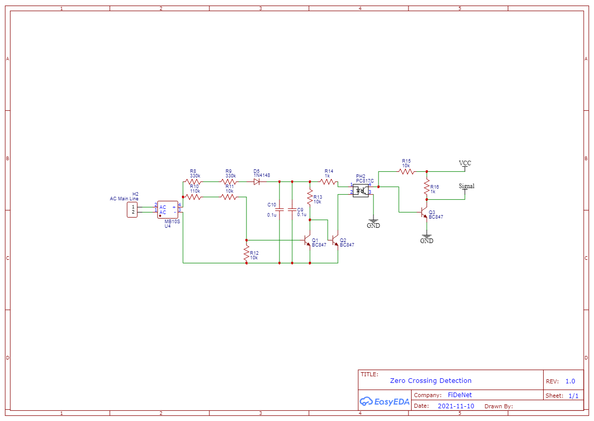
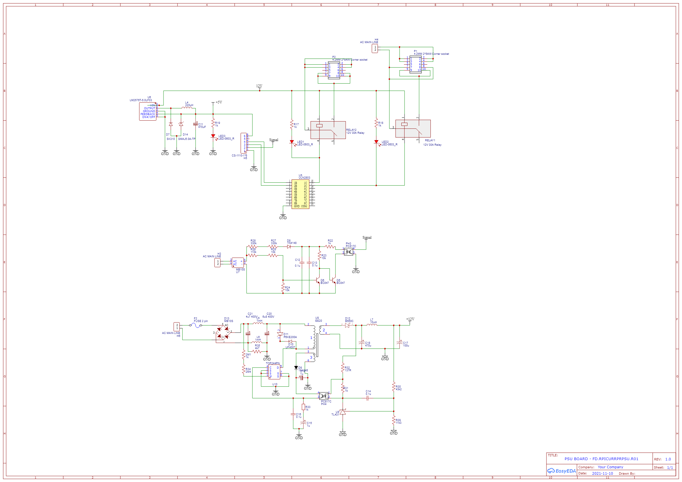
Sensor board has 5 BNC connectors. One of them is Zero Cross Detector output. It is isolated from high voltage. Two of them are AC main current sensor out (ref + current output). So any ossciloscope can be tied to box and track changes in current of load.
The last two BNC's are output of low voltage current sensor output and reference output. As the same of above, ossciloscope can track current of load. All the reference and current outputs are isolated from voltage source. By the help of HMSR30 and GO-10 SME sensors, current can be measured galvanically. There is no touch of the live wires.
MCP3204 is a 4 channel 12 bit ADC chip. Output of the current sensors are tied to BNC jacks and input of the MCP3204 chip. When I did some tests and saw that MCP3204 can take sample nearly 1600 times in a second. It is good for DC current but not bad for AC main. It is not perfect but acceptable.
Pi Zero reads MCP3204 over spi port. Pi Zero reads adc chip and subtract current value from reference value. Go-10 chip gives 1.65 Volt for reference. If a current flows over chip about 1A, reference voltage is constant but current output voltage drops or rises 80mV/A. Current output voltage drops 80mV if direction of current is P- to P+ pins, output voltage rises 80mV/A if direction of current is P+ to P- pins,
HMSR30 works as the same of Go-10. But resolution is 26.6mV/A instead of 80mV/A.
Example:
5 Apms on Go-10, direction is P+ to P-, sensor output is 1.65V + 5 * 80mV = 1.65V + 0.4V =2.05V
If direction is reverse, output is 1.65V - 5 * 80mV = 1.65 - 0.4 = 1.25V
There is an important point at here. If you sample 100 times in a second, you will probably have a random current value. Because there are 100 alternance (for 50Hz) in a second. If you read 100 times in a second you might be read at zero cross, or rising ramp, middle of the alternance or falling ramp of alternance. For avoiding from this situation we should read increase sample count much as possible as. I made some test and read 1600 times in a second. I think it is not perfect but acceptable.
I placed an HMTRP-433 RF module on pcb. With the help of this module, I can start (and stop ) to measure current using a remote control unit. I will desgn it later.
I want to track the changes in current by the time. I will keep the reults at a text file, database or Excel file. So i can easily make a chart from these values like below.
(sample graphic is taken from https://www.ametherm.com/wp-content/uploads/2019/02/Vacuum-Motor-without-inrush-current-vs-with-inrush-current.png)
I am developing codes, it has not been finished. I will share codes at github and give link at here.
I ordered pcbs from PCBWAY. Pcb quality is excellent. Thanks to PCBWAY for high quality pcb manifacturing and supporting my projects.
I shared this project's pcbs at PCBWAY Shared Projects. Anyone who likes this project can order pcb's from the link below.
https://www.pcbway.com/project/shareproject/Raspberry_Pi_Current_Measure_and_Record_Probe.html
I used plastic box to avoid injuries from main plug. Plastic case is manifactured by Altinkaya Electronic Enclosure.
Thanks to Altinkaya Electronic Enclosure send a sample for this project.
Here is the link of plastic enclosure.
https://www.altinkaya.com.tr/IP-67-Plastik-Panolar/EC-1624-11.html
I made some revision and mistakes on pcb. There is no need to make revision on pcb but mistakes on pcb is lowering resolution of current measurement.
I want to get a clear 3.5V reference for MCP3204 reference input. I designed a TL431 voltage source for it. But this circuit caused triangle tricks at voltage. If I make revisions on this project or redesign the pcb, I will use Pi Pico or another ADC chip to which can sample faster rates than MCP3204. So I can take 10.000 sample in a second.
Then I disabled the TL431 circuit. The reference voltage is 5V.
Hope to be useful for one's.


Comments
Please log in or sign up to comment.