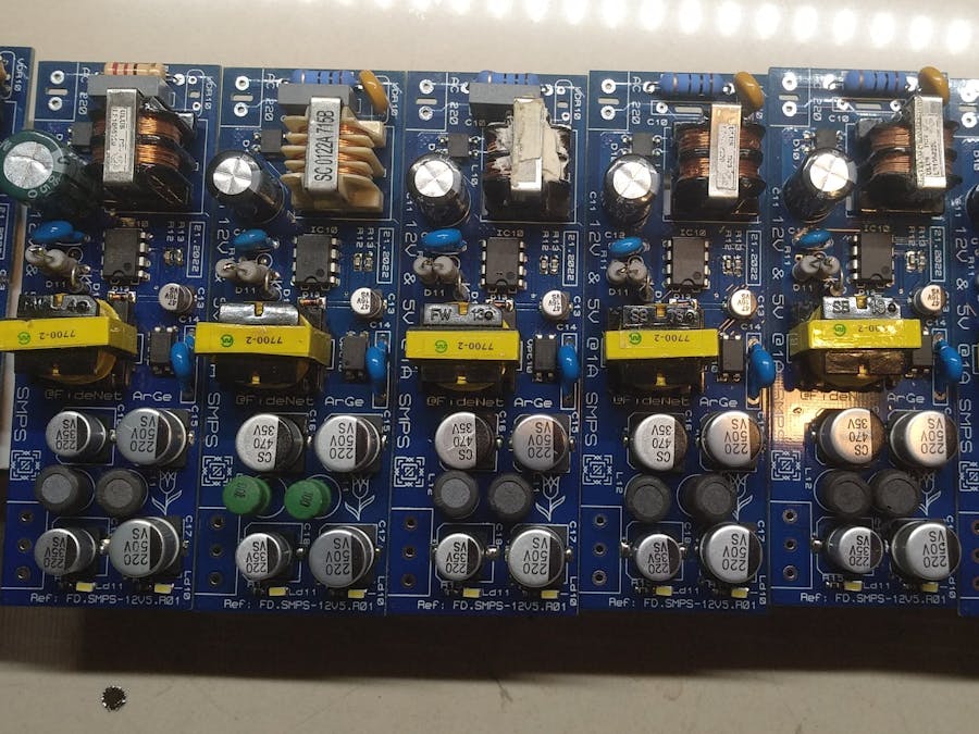
Some projects need to work with AC main supply. Sometimes adapters can be used to feed the circuit but it is useless. Because I don't have so much adapter to fit in the projects. So I designed my smps pcb to use my forward projects. I will design my forward projects using this smps circuit.
The transformer in this project is a ATX power supply standby transformer. It has 5V and 12V output.
I used this transformer. I redesigned output. TL431 is output controller for Viper22A. Transformer has 2 output. 5V and 12V. I need regulated 5V. I revised output for getting regulated 5V.
After finishing pcb design, I ordered pcb from PCBWAY. PCB manifactured and delivered in 10 days. Thanks to PCBWAY for high quality pcb manifacture and steel stencil. This stencils makes my work so easy to assmeble smd components.
Above 3 photos both smps's both outputs are loaded. Only 1 output is measured but both outputs are loaded and approx 11W power is spended over the resistor. Maybe more power can be delivered by smps but I didn't load above 12watts.
I have seen some cases with smps.
- When singly 12V output is loaded about 1A, smps goes to hiccup mode. Because current is delivered to secondary side but there is no feedback from feedback circuit. So Viper22A goes to hiccup mode.
- When singly 5V output is loaded about 1.5A, voltage drops approx 4.86V and can't rise to 5V.
I need <1A at 5V channel and <0.5A at 12V channel for driving something like a couple of relays.
I loaded smps conditions at pictures above and tracked temperature and output voltage. I don't have thermal camera but there was no abnormal heat and change at output voltage.
This pcb can be ordered by the following link on PCBWAY.
https://www.pcbway.com/project/shareproject/viper22A_5V_12V_SMPS_Circuit_0c248d23.html
Thanks to PCBWAY for supporting my projects.


Comments
Please log in or sign up to comment.