The Idea....
I was asked if i could come up with a way to measure and test multiple cells or battery packs for battery manufacturers to be able to test their batteries for research purposes, The unit that they had available could only do one battery at a time and it took 2 to 4 hours to complete the tests and a machine that could do more batteries cost around R 40 000 (South African Rand) So i set out to make life a bit easier and also realized that this unit is very useful for testing different types of batteries for my hobby R/C stuff so i can determine the best batteries to use for my 'toys' ?
How it works....
I made use of 10 INA219 current sensors to do my individual measurements, now if you look on the adafruit web site you will see they tell you that you can only add 4 of this units to one micro-controller's I2C line because of the addressing but its actual more like 20. If you read the INA219 IC Datasheet they explain how to change the Hex addresses just by moving and connecting different wires between GND, VCC, SCL and SDA, luckily i have made it easy for you and i uploaded the connections you have to make on the INA219 breakout board to make it easy for you.
Just follow the connections like above on the jumper pins A0 and A1 of the current sensors.
The current sensors sends all the recorded data to the Adafruit feather 32U4 Adalogger where it then gets displayed in any Serial IDE of your choice like Hyper term or cool term and it also gets saved as raw data to your Micro SD card that is on-board the Adalogger ready to be added to an excel file for later use.
I added in a DS3231 RTC so that i can record the times and dates that the measurements are taken.
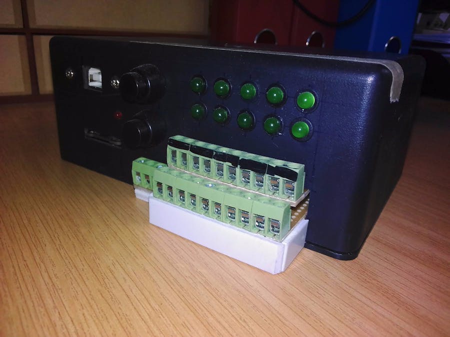
Making use of Vera Board i placed all the current sensors in an upright position to save some space as well as the RTC, i Used screw down terminals for the battery connections and Two momentary push buttons, one is the start button and the other the reset or stop button. I connected an LED to pin 13 to indicate when data is being written and saved,
Each battery terminal also has an LED connected via a 100R resistor, this will only come on when a battery is connected in order to indicate a live connection.
Making use of the unit
Connect 10 single cells up to the bottom positive ports and top negative ports irrespective to test each cells discharge efficiency and power consumption, The same applies for battery packs, Connecting a charger and a battery/battery pack in series with the terminals will record and test charge efficiency and time , I also added a Dallas Temperature sensor port with a 4K7 resistor, up to 10 temp sensors can be connected to this port simultaneously and they will automatically address them selves, by doing this you can now measure the battery temperature during charge and discharge.
I then placed everything in a simple black plastic enclosure to tidy everything up.
Download Cool Term as your IDE,
Open > Connections >>> Capture to text file >>> Start..
This will start to record your data after you push start on the unit..
NB Remember to push stop in cool term to save the file otherwise it wont save
The file should automatically save to your documents
Also make sure you have the correct port and Baud rate selected,
After your file has finnished saving open excel, and go to
>> File >>> Open.. in the open box of excel where you select the file type to open select 'all files' then the Cool term file will come up. Select this file...
After the file opens just chose your prefered settings for viewing the data in a graph format and hit enter.....
And there you go... Neat information in Digital format..


_3u05Tpwasz.png?auto=compress%2Cformat&w=40&h=40&fit=fillmax&bg=fff&dpr=2)
Comments
Please log in or sign up to comment.