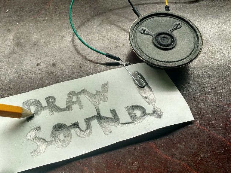
Drawing is fun, so is making music... So let's combine them so we can draw sounds! It's simple once you understand how it works. First we use a graphite pencil, the graphite is conductive but still is slightly restive. The Arduino board measures the resistance between the pencil and paper clip then converts it into a pitch that it then sends to the speaker. I added an potentiometer to further control the pitch, also it will not play unless there is contact from the pencil. You can make tons of different designs, just remember the thinner the line the more resistance there will be. I think it's time to begin!!
Step 1: PartsYou will need the fallowing parts for this project:
- Arduino (UNO, NANO, MEGA, pretty much any of them)
- Speaker (I'm using a 8ohm, 0.5w speaker)
- potentiometer
- led (optional)
- 10k resistor
- wires
- pencil
- paper clip
- Tape, Heat shrink, or anything to hold the wire to the pencil
- breadboard
Tools:
- Drill with small drill bit
- knife
- soldering iron
- solder
- computer with Arduino IDE
We are going to make the pencil and paper clip for the project. This is relatively simple, drill a small hole in the pencil slightly less than halfway through, insert the wire then bend up. Now holding the wire in place, place tape or heat shrink on top and make sure it is tight. Now test it with anything to make sure that the wire is making contact. if not redo it. Also find a small paperclip and solder a wire to it, if you do not want to solder just rap the wire around it. The build is now done!!
Step 3: Build (Part 2)Below I have included a schematic on how everything is put togeather
The wires on 9 and 10 are the wires that will be connected to the pencil and paper
Connections:
- Arduino Pin 3 ----------> Speaker +
- Arduino Pin 5 ----------> LED (optional)
- Speaker - ---------------> GND
- Potentiometer pin 1 ---> VCC 5v
- Potentiometer pin 2 ---> Arduino A0
- Potentiometer pin 3 ---> GND
- Pencil -------------------> VCC 5v
- Paper Clip --------------> A1
- Resistor ----------------> A1 and GND
I put together this simple code, as I explained in the introduction it reads the analog value of A1 and converts it into a pitch to send to the speaker:
#define speaker 3
#define led 5
#define pot A0
#define input_pin A1
#define pitch_min 50
#define pitch_max 4978
void setup() {
  Serial.begin(9600);
}
void loop() {
  int input_pitch = analogRead(pot);
  int input = analogRead(input_pin);
  int pitch_adj = map(input_pitch, 0, 1023, -500, 500);
  int pitch = map(input, 0, 1023, pitch_min, pitch_max);
  int b = map(input, 0, 1023, 0, 255);
  analogWrite(led, b);
  Serial.println(pitch);
  int final_pitch = pitch + pitch_adj;
  if(final_pitch > pitch_max){
    final_pitch = pitch_max;
  }
  if(final_pitch < pitch_min){
    final_pitch = pitch_min;
  }
if(final_pitch != pitch_min){
    if(pitch != pitch_min){
      tone(speaker, final_pitch, 30);
    }
  }
  delay(25);
}
Draw a filled in rectangle on one side of a piece of paper, big enough for the paperclip. Now touch the paper near the paperclip (on the graphite) you should hear sound. Now move it further away the pitch should decrease. Hooray you've done it! There are endless designs in your imagination that you can draw to make sounds.
If no sound comes out make sure all your wiring is correct, if it is make sure your potentionometer is all the way high it now should work! If it doesn't let me know in the comments and i will try to help.
Step 6: Did you like this project?As you probably know writing an tutorial is hard work it takes days of editing, I'm hoping you enjoyed this project and would vote for me in the circuits contest. Thanks again for reading this project!


Comments
Please log in or sign up to comment.