Now your plants don't have to wait for you to water them.
PartsHere is a list of parts you will need to make this:
- DC water pump
- Single channel relay
- Soil moisture sensor (capacitive recommended)
- Tube
- Water in a container
- Arduino
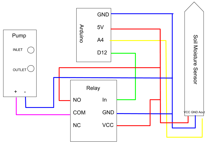
The pump delivers water from your container into your plant. You may have to refill your container every once in a while. The relay is used to trigger the pump. The soil moisture sensor detects the amount of water in the soil. The tube is used to take water from the pump's outlet onto the plant.
Here is a product from amazon that has all of the necessary hardware (except for the arduino): https://www.amazon.com/gp/product/B07TLRYGT1/ref=ppx_yo_dt_b_asin_title_o02_s00?ie=UTF8&psc=1
Physical SetupStart by soldering the connections shown in the circuit diagram. After, s the soil moisture sensor into the soil near your plant. If your plant is outdoors, you have to protect your electronics from getting rusted or damaged. To avoid corrosion of the soil moisture sensor, you a capacitive one. Glue or tape the relay module and the arduino to a nearby wall. In my case, I glued it to the pot which had my plant in it. Place the water container in an accessible place. It should be close enough to the arduino and relay so the wires can connect to it and also should be easily to refill. Fill the container with water. Put the pump in the water with the inlet facing down. Attach the tube to the outlet and put it facing the plant. With that, the physical setup is done.
CodeThe code not very difficult. Here's an overview of the commands used:
This first line defines a variable of what soil moisture level the pump should turn on. In other words, this is when the soil is too dry. This will change depending on your plant and the input voltage. For me, that variable was 280.
const int dry = 280;
These next two lines define the pins you'll use for your pump and the soil moisture sensor. In my case, D12 and A4. pumpPin has to be a digital pin, while soilSensor has to be an analog pin.
const int pumpPin = 12;
const int soilSensor = A4;
Now, onto setup().
The next line defines pumpPin as an output. This is important because you have to write to this pin.
pinMode(pumpPin, OUTPUT);
The following line sets soilSensor as an input. This is important because you have to read data from this pin.
pinMode(soilSensor, INPUT);
After that, you have to begin the serial monitor to see what you sensor is reading.
Serial.begin(9600);
Now, onto loop().
You have to make a variable to store data you are receiving from the pin you set as soilSensor. Then you can print that value onto the serial monitor to see what that value is. The second part is optional, but helpful for debugging.
     int moisture = analogRead(soilSensor);
     Serial.println(moisture);
Then we have to make and if else statement. The part inside the parentheses is the condition for the if statement to be true. In this case, it is if the current soil moisture is less than or equal to what you defined as dry.
if (moisture >= dry){
Inside the brackets is what code is to be run if the if statement is true. For us, we have to turn on the relay that activates the water pump. After that, close the brackets.
   digitalWrite(pumpPin, LOW);
   }
After that, we need and else statement. An else statement is run when the if statement is false. All that needs to be inside this else statement is a command to turn the relay off, so the plant is not receiving excess water.
 else{
   digitalWrite(pumpPin, HIGH);
 }
} #remember to close the loop function
That's it for the code.


Comments
Please log in or sign up to comment.