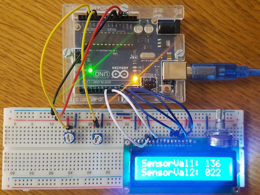
I have been tinkering with Arduino for a while now, mostly with LED's and stuff and finally bought my first LCD and decided to test it with one sensor which worked fine, however I found very little projects where it shows multiple sensors being used so I decided to build this one.
This project uses 2 potentiometers that are connected on a breadboard to an Arduino and LCD. The end result is that the LCD should indicate the values of both the potentiometers when they are adjusted.
The Liquid Crystal DisplayBefore starting the configuration, let's look and the LCD closely and see what the 16 pins are for:
- GND - Ground Connection
- VCC - +5V Connection
- VO - analogue pin used for screen brightness, connects to Potentiometer.
- RS - tells the LCD what will be written to it.
- R/W - the read/write pin (normally hardwired to ground).
- E - tells the LCD the data is ready to be written.
- D0 to D7 - bus lines for the LCD, this is where your data is passed from the Arduino to the LCD.
- A - +5V Connection for the backlight of the LCD.
- K - the ground pin for the backlight of the LCD.
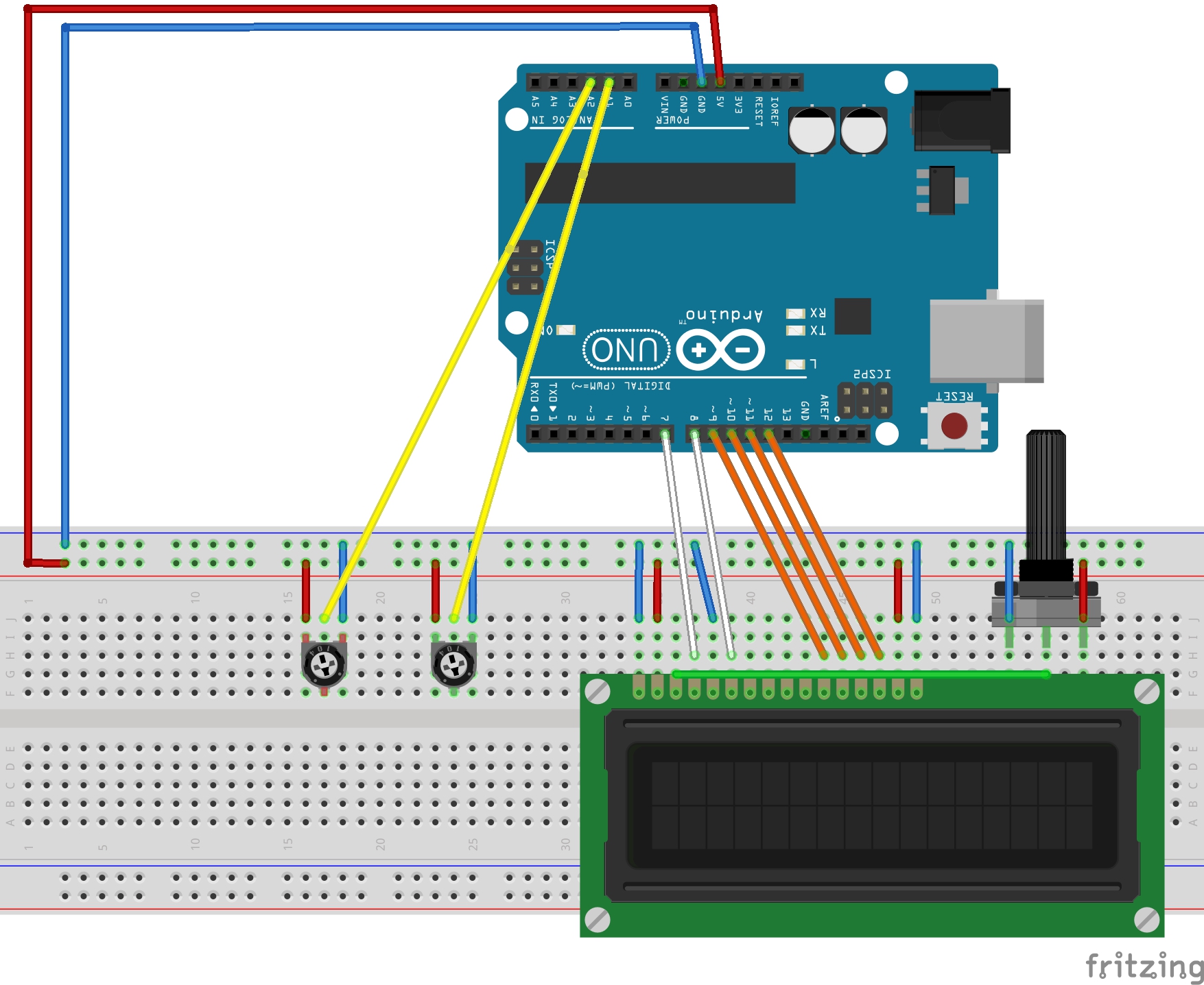
Now we can start making connections on and to the breadboard. Below is a step-by-step guide:
- Connect the 10K Ohm potentiometer (this potentiometer is used to control the contrast of the LCD). The middle pin of potentiometer is connected to the VO pin and the other two wires are connected to +5V and ground on the breadboard.
- Connect pin-A to the +5V and pin-K to ground on the breadboard.
- Connect pin-D7 to digital pin 12, pin-D6 to digital pin 11, pin-D5 to digital pin 10 and pin-D4 to digital pin 9. (Digital pins on the Arduino).
- Connect pin-RS to digital pin 7 on the Arduino.
- Connect pin-RW to ground on the breadboard.
- Connect pin-VSS to ground on the breadboard.
- Connect pin-VDD to +5V on the breadboard.
- Connect pin-E to digital pin 8 on the Arduino.
- Place the first potentiometer on the board and connect the center pin to Analog Pin 1 on the Arduino and the other pins to ground and +5V on the breadboard.
- Place the second potentiometer on the board and connect the center pin to Analog Pin 2 on the Arduino and the other pins to ground and +5V on the breadboard.
See the picture below for the potentiometers that are to be used.
Upload the code below to your Arduino and adjust your potentiometers as you wish. The LCD display will show 2 lines with the values of the potentiometers. You can adjust the B10K potentiometer to ensure the contrast of the LCD is perfect to read the values.
And that's it! Thank you for checking out my project and please feel free to comment on how I can make it more useful.


_ztBMuBhMHo.jpg?auto=compress%2Cformat&w=48&h=48&fit=fill&bg=ffffff)


Comments
Please log in or sign up to comment.