


Hardware components | ||||||
| × | 1 | ||||
Software apps and online services | ||||||
 |
| |||||
| ||||||
| ||||||
| ||||||
 |
| |||||
This work assumes you have read the full ASURO manual and have a working hardware built (self-test successful). (You will not need this to understand most of the text but I'll sometimes refer to the manual for more detailed instructions.)
Please note that before I started this project I was pretty much an Arduino noob and this work was created in only two weeks so be aware that I may have made some mistakes or solved things the wrong way. Same goes for this article, it is really just a collection of all the stuff I learend then a tutorial. Also please note that I am german so my English is not perfect. Any feedback will be much apprechiated.
Hardware ModsThese mods have been done on a otherwise unmodified ASURO with an Atmega8. Read the entire Document including the code before making any modifications.
- Recommended
Changing R18 and R20 from a 4k7 resistor to a 6k9 (4k7 + 2k2 in Series) gives a cleaner motor encoder output for digitalRead. (lowers LOW signal to get a clean reading)
Cutting R24 to remove interrupt input for the switches. The resistor is not required and leads to bugs.
- Optional
Adding a bride from analog pin A0 (23) to interupt pin 1 (5) and from analog pin A1 (24) to interrupt pin 0 (4) makes reading the motor encoder more accurate. For this mod the interrupt pins should be bent up to no longer have contact to the board but only the bridges. You will loose the ability to switch the Status Led red with with mod. Please note that you will have to modify the provided functions following the instructions under "Code Section | Failed Speed Test Code"
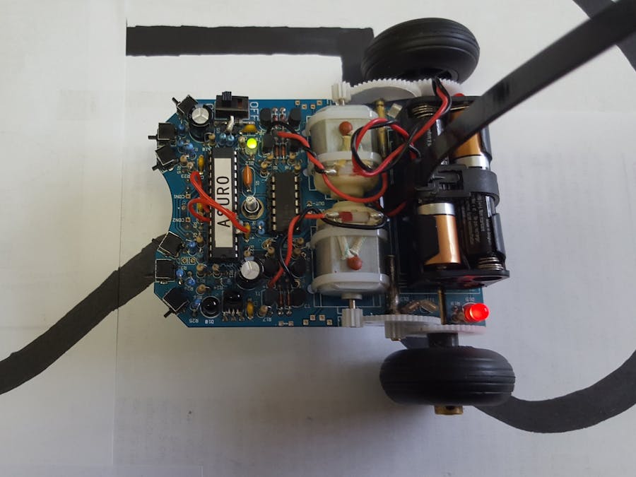
I also modified the black and white stickers for the gears to be half black and half white to reduce the amount of points per rotation the code has to track. But even with this and the interrupt mod I have not been able to properly count the motor rotations.
ASURO PinoutIf you want to control the individual pins on the ASURO yourself, here's a table what each pin does:
Pins unnecessary for programming have been left out, refer to the full circut diagram for these.
Digital pins return LOW at max 0.2*operating voltage and HIGH at min 0.6*operating voltage
Analog pins return a value between 0 and 1024 depending on the voltage applied
1 (RESET)
2 (DP0)  	-	Infrared IN
3 (DP1)  	-	Infrared OUT
4 (DP2)  	-	Status LED red (Disabled with optional mod, interrupt pin)
5 (DP3)  	-	Switches interrupt (Disabled with recomended mod, interrupt pin)
6 (DP4)  	-	Left Motor Backward(this pin + PWM(15) makes it move backward)
7 (VCC)
8 (GND)
9 (OSC1)
10 (OSC2)
11 (DP5)	-	Left Motor Forward(this pin + PWM(15) makes it move forward)
12 (DP6)	-	Linesensor LED
13 (DP7)	-	Encoder LEDs (activate or the encoders won't work)
14 (DP8)	-	Status LED green
15 (DP9) 	-	Left Motor Speed Control(PWM, analogWrite( 9, [0-255] ); )
16 (DP10)	-	Right Motor Speed Control (PWM, analogWrite( 10, [0-255] ); )
17 (DP11)	-	Part of the Infrared Send Circut
18 (DP12)	-	Righ Motor Backward(this pin + PWM(16) makes it move backward)
19 (DP13)	-	Right Motor Forward (this pin + PWM(16) makes it move forward)
20 (AVCC)
21 (AREF)
22 (GND)
23 (A0)  	-	Right Encoder Light Sensor
24 (A1)  	-	Left Encoder Light Sensor
25 (A2)  	-	Right Line Sensor
26 (A3)  	-	Left Line Sensor
27 (A4)  	-	All Switches input (Different value depending on switch(es) pressed)
28 (A5)  	-	Battery Sensor
From my experience in Windows 10 the Software provided with ASURO is partly completley outdated and partly not even working correctly. Because of this I have found the programs mentioned in required Software to be a suitable replacement. Following here are the instructions how to make the software work (tested on Windows 10). Same goes for the Asurino libary. I have found it to be unreliable and overcomplicated (it is still used here for having the right board and bootloader options). Because of this I wrote my own if from of functions. I have used functions instead of a libary as I am not familiar with how to make a libary. If someone could make my work a libary I would be super grateful.
- Install the USB drivers, follow the ASURO Manual
- Download HTerm, unzip it and lauch it. Select the highest COM-Port number (in my case Com3), make the settings mentioned in the ASURO Manual for Hyperterminal, which is an old Windows XP software, HTerm is a well-working replacement for that.
(ASURO Manual chapter 5.1: Baud 2400, Data 8, Stop 1, Parity none)
(Further useful settings: Newline at CR+LF, Autoscroll true, Input as Ascii, Send on enter LF)
- Select the appropriate COM-Port in HTerm and click connect. Enter something in the send line and press send. If the LED on the USB infrared stick flickers yellow the driver install should have been successful, for further testing refer to the ASURO Manual
- Install the Arduino IDE from the provided download link, do not use the Windows store app but the.exe installer.
- Install the Asurino libary following the readme document. Also load it corectly following the "Building an Asurino Skech" instructions.
- Go into the Arduino Settings (ctrl+, ) and enable "Display line numbers" and "Code Folding"
- Copy the code provided under "Functions to Import" in this document into Arduino and collapse all functions.
- When you compile the code the warnings below are normal and do not affect the working code.
In file included from C:\Program Files (x86)\Arduino\hardware\arduino\avr\cores\arduino\wiring_private.h:31:0,
                from C:\Program Files (x86)\Arduino\hardware\arduino\avr\cores\arduino\wiring_digital.c:26:
C:\Program Files (x86)\Arduino\hardware\arduino\avr\cores\arduino\Arduino.h:195:0: warning: "PE" redefined
#define PE 5
^
In file included from c:\program files (x86)\arduino\hardware\tools\avr\avr\include\avr\io.h:350:0,
                from C:\Program Files (x86)\Arduino\hardware\arduino\avr\cores\arduino\wiring_private.h:26,
                from C:\Program Files (x86)\Arduino\hardware\arduino\avr\cores\arduino\wiring_digital.c:26:
c:\program files (x86)\arduino\hardware\tools\avr\avr\include\avr\iom8.h:534:0: note: this is the location of the previous definition
#define PE 2
^
Here I'll explain how to flash your code to the ASURO.
- Press Ctrl+Alt+S or go to Sketch | Export compiled Binary
- Once compiling is done and the compiler verified your code has no errors start Flash.exe from the ASURO CD
- Like in HTerm select the appropriate COM-Port.
- Go to select file and select the.hex file that got created in your project folder. (The folder the sketch is saved in)
- Click program. You'll see it opens the COM-Port, then it builds Ram. It will try to connect to your ASURO after that. Bring the ASURO close to the sender with the infrared LEDs facing it and turn the ASURO on. The Flash tool should connect and start flashing. For more details how to use the flash tool refer to the ASURO Manual.
Here are all the functions I wrote and how to use them.
void motorSpeedR(int SpeedR)
void motorSpeedL(int SpeedL)
Takes an input from -255 (full reverse) to +255 (full forward) for the right/left motor.
The void motorSpeed[R/L]_() functions are the basic motor controls, the normal functions shown above feature a short 'startup-sequence' if you give the motor a value below 100. 'startup-sequence' here means that the motors get set to max power for 50ms to get the motors rotating, then the requested value is sent to the motors. If you wish to not use this feature use the _-functions or comment the code block responsible for it.
void motorSpeed_(int L, int R)
Combines motorSpeedR_() and motorSpeedL_() the ones without the 'startup-sequence'
void motorSpeed(int L, int R)
Combines motorSpeedR() and motorSpeedL() into one function.
int readEncoderR()
int readEncoderL()
Returns the analogRead of the right/left Encoder.
boolean readEncoderRdigital()
boolean readEncoderLdigital()
Returns a boolean value if the digitalRead is reading high or low.
int readSwitchesRaw()
Returns the analogRead of the switch input pin
int getSwitches()
Returns the number of the switch pressed from 1(far right) to 6(far left). Returns 0 when no switch is pressed. Please note that pressing multiple switches simultaneously will lead to inaccurate readings. This function also uses a filter to get cleaner results. I have managed to dial it in in a way that at least for my ASURO the switch readings are almost perfect.
boolean switchesPressed()
Returns a true value if any switch is pressed.
int getLineSensorR()
int getLineSensorL()
Returns the analogRead of the right/left Linesensor. For using this it is recomended to enable the front LED.
void setLedFront(boolean onoff)
Takes a boolean value to set the Linesensor LED on/off.
void setStatusLedGreen(boolean onoff)
Takes a boolean value to set the green part of the Status LED on/off. Can be mixed with the red Status LED.
void setStatusLedRed(boolean onoff)
Takes a boolean value to set the red part of the Status LED on/off. Can be mixed with the green Status LED. This function does not work when you are using the interrupt mod.
Example ProgramsThe examples below are intended to serve as Inspiration for you and demonstrate how the functions work. (see Code Section | Example 1/2)
Experiments with Stepper-Like ControlI tried a lot to get the Light Barrier 'encoders' working properly, but I could never quite make it work. No matter what I tried the counting system was never fast or accurate enough to count all steps. The general Idea was to measure the frequency of rotation of the wheel and then to use a PID Controller to be able to make a true speed input instead of a power input. After over a week I have not managed to make this work, if you want to continue this I have included some Code that was meant to be used for that task below under "Failed Speed Test Code"
ConclusionAt first I faced many errors and not working programs. But now, after I have made my own programs work and wrote my own functions I finally got a working a reliable programmable robot.


Comments
Please log in or sign up to comment.