

Hardware components | ||||||
 |
| × | 1 | |||
 |
| × | 1 | |||
 |
| × | 1 | |||
 |
| × | 1 | |||
Software apps and online services | ||||||
| ||||||
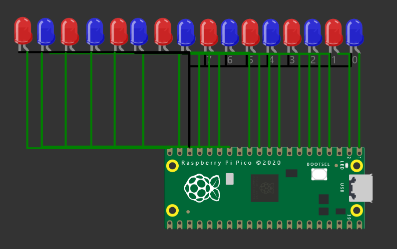
I have tried to create 10 LED patterns using the free Pi Pico Simulator. I have to admit that there will be some mistakes or might have missed scope for improvements. I appreciate your feedback to make this better.
I have used Wokwi Raspberry Pi Pico Arduino Simulator to code, compile and see the results.
- 16 LEDs are used - 8 RED LEDs and 8 Blue LEDs
- You can change the LED colours using diagram.json file
- visit the link above and sub links on the above page for more information on the online Pico simulator
- Pico is a small powerful and versatile board from Raspberry Pi. It has RP2040 MCU on it which has a cortexM0+ processor.
- for more details, refer to Pico datasheets and user guide from the below links
https://datasheets.raspberrypi.org/rp2040/rp2040-datasheet.pdf
https://datasheets.raspberrypi.org/pico/getting-started-with-pico.pdf
https://hackaday.io/project/177082-raspberry-pi-pico-emulator
The simulated output on the online Pi Pico Simulator/**
Controlling the Pi Pico GPIO with direct register access (SIO registers + IO Bank 0 registers)
Code example from the Raspberry Pi Pico Deep Pico - The Deep Dive course:
https://hackaday.io/course/178733-raspberry-pi-pico-and-rp2040-the-deep-dive
*/
/* Enables the SIO function for the given pin, by writing to the relevant CTRL register.
(e.g. GPIO0_CTRL at 0x40014004) */
void enable_sio(int pin) {
uint32_t *PIN_CTRL_REG = (uint32_t*)IO_BANK0_BASE + pin * 2 + 1;
*PIN_CTRL_REG = 5; // 5 = SIO function
}
void setup() {
// Enable the SIO function for pins GP0 to GP7
for (int i = 0; i < 16; i++) {
enable_sio(i);
}
// Enable output on pins GP0 to GP7:
// sio_hw->gpio_oe points to 0xd0000020 (GPIO_OE)
sio_hw->gpio_oe = 0b1111111111111111;
// Set initial pin pattern
// sio_hw->gpio_out points to 0xd0000010 (GPIO_OUT)
sio_hw->gpio_out = 0b1010101010101010;
}
void loop() {
#if 0
//pattern 1
for (int i = 0; i < 20; i++) {
sio_hw->gpio_togl = 0b1111111111111111;
delay(420 - 20 * i);
}
//pattern 2
for (int i = 0; i < 16; i++)
{
sio_hw->gpio_out = 65535 >> i;
delay(300);
}
//pattern 3
for (int i = 0; i < 16; i++)
{
sio_hw->gpio_out = (65535 >> i);
sio_hw->gpio_togl = 0b1111111111111111;
delay(300);
}
//pattern 4
for (int i = 0; i < 16; i++)
{
sio_hw->gpio_out = 1 << i;
delay(100);
}
#endif
//pattern 5
for (int i = 0; i < 16; i++)
{
sio_hw->gpio_out = 32767 >> i;
delay(100);
}
//pattern 6
sio_hw->gpio_out = 65535;
for (int i = 0; i < 16; i++)
{
sio_hw->gpio_togl = 0b1111111111111111;
delay(200);
}
//pattern 7
sio_hw->gpio_out = 65280;
for (int i = 0; i < 8; i++)
{
sio_hw->gpio_togl = 0b1111111111111111;
delay(300);
}
//pattern 8
sio_hw->gpio_out = 61680;
for (int i = 0; i < 16; i++)
{
sio_hw->gpio_togl = 0b1111111111111111;
delay(300);
}
//pattern 9
sio_hw->gpio_out = 52428;
for (int i = 0; i < 16; i++)
{
sio_hw->gpio_togl = 0b1111111111111111;
delay(300);
}
//pattern 10
sio_hw->gpio_out = 43690;
for (int i = 0; i < 16; i++)
{
sio_hw->gpio_togl = 0b1111111111111111;
delay(300);
}
}Please hop on to the discord channel for any support related to the pico simulator or coding in general related to the project.
Share your interesting projects and browse through several curious projects from fellow developers and makers on Facebook Wokwi Group!
Stay Safe!
Don't stop learning!
#wokwiMakes


Comments
Please log in or sign up to comment.