


Hardware components | ||||||
 |
| × | 1 | |||
 |
| × | 1 | |||
 |
| × | 1 | |||
Today we are going to see How Control an LED Using Espo8266. The GPIO pins of the ESP8266 can be configured to realize many functions: inputs, outputs, PWM outputs, and also SPI or I2C communications. This to begin with the project will teach you how to utilize the GPIO pins of the chip as outputs.
Required Component :
5. 5mm LED
This book will help you to gain more knowledge of the Internet of Things with ESP8266
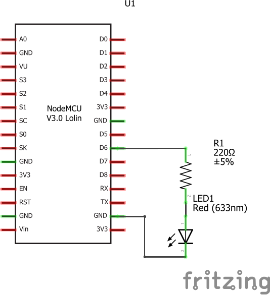
Circuit Diagram :
interface the LED with the resistor to the ESP8266 board. To do so, the primary thing to do is to put the resistor on the breadboard. At that point, put the LED on the breadboard as well, interfacing the longest PIN of the LED (the anode) to one PIN of the resistor And interface the other end of the resistor to GPIO PIN 5 of the ESP8266, and the other end of the LED to the ground now going to light up the LED by programming the ESP8266 chip
Code Control LED Espo8266:
#include <ESP8266WiFi.h>
void setup() {
// Set GPIO 5 as output
pinMode(5, OUTPUT);
// Set GPIO 5 on a HIGH state
digitalWrite(5, HIGH);
}
void loop() {
}
This code simply sets the GPIO PIN as an Output, and after that applies a HIGH state to it. The High state means that the PIN is active, which positive voltage (3.3V) is connected to the PIN. A Low state would mean that the output is at 0V.
You’ll be able presently to copy this code and paste it into the Arduino IDE. You should quickly see that the LED lights up. You’ll be able to close it down once more by using digitalWrite(5, Low) within the code. You may also, for example, alter the code so the ESP8266 switches the LED on and off every second.
Visit to get more tutorials on IoT project
INTERNET OF THINGS


Comments
Please log in or sign up to comment.