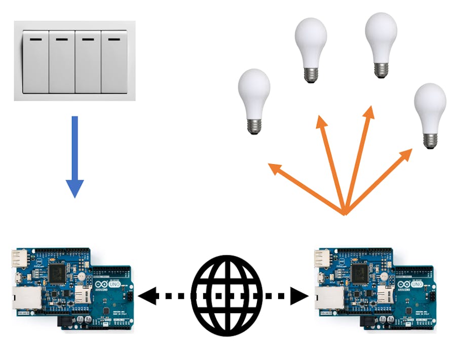
In real life, we usually have devices placed at different areas (e.g, like light bulbs in different rooms). The traditional way to control those devices is via locally installed buttons/switches.
Nowadays you can even take control via smart phone application, web browsers, etc, but that's a different story. In this project, I just want to show you how to make a simple centralized control panel. That means, you can sit in one room, with all the buttons/switches on the table, and use them to control anything from anywhere.
In fact, this type of applications can be called "Internet Switches", whereas the input information is forwarded through TCP/IP network, and then on the other side over the Internet, the output control signal is made based on those input information.
Enough talking, now I am going to show you how I made an Internet switches. It allows me to use switches to remotely control devices (toggle a lamp ON/OFF) via the Internet.
II. How it worksThings are quite straightforward. I made a simple demonstration project with two Arduino boards, one work as a controller and another work as an actuator.
- Controller board: One Arduino is used at the control side. It receives the input signal from the switches, then transfers those input signal via the Internet with the help of PHPoC Shield. This controller board is a combination of one Arduino + one PHPoC Shield (for network function) + one PHPoC Smart 4-Port Input Board (for reading input signal), stacked together. The input board is connected with a switch. The board detects the input state from the switch and forward any input changes to the actuator board.
- Actuator board: I make another Arduino board to receive the input signal and then output that signal to control the lamb. This board consists of one Arduino, one PHPoC Shield, and one PHPoC Smart Relay Board.
The control board communicates with the actuator board via TCP connection, one works as a TCP client and the other as a TCP server. That means we can put the controller and actuators at long-distance places and they will still work, because they can connect to each other via the Internet.
Well, I made this project with the hardware I have T_T, so only one input port (connected with the switch) and one relay output port (connected with the lamb) are used. Actually this can be extended much more than that with more hardware equipment.
Two-way control can be made. With additional effort, we can make the controller board work as an actuator board also, and vice versa.
Other actuators can be added, that means one controller can be used to control many actuator boards.
Demonstration
Learn more about relay in this tutorial


_ztBMuBhMHo.jpg?auto=compress%2Cformat&w=48&h=48&fit=fill&bg=ffffff)
_wzec989qrF.jpg?auto=compress%2Cformat&w=48&h=48&fit=fill&bg=ffffff)


Comments