//GPIO declarations
//-=-=-=-=-=-=-=-=-=-=-=-=-=-=-=-=-=-=-=-=-=-=-=-=
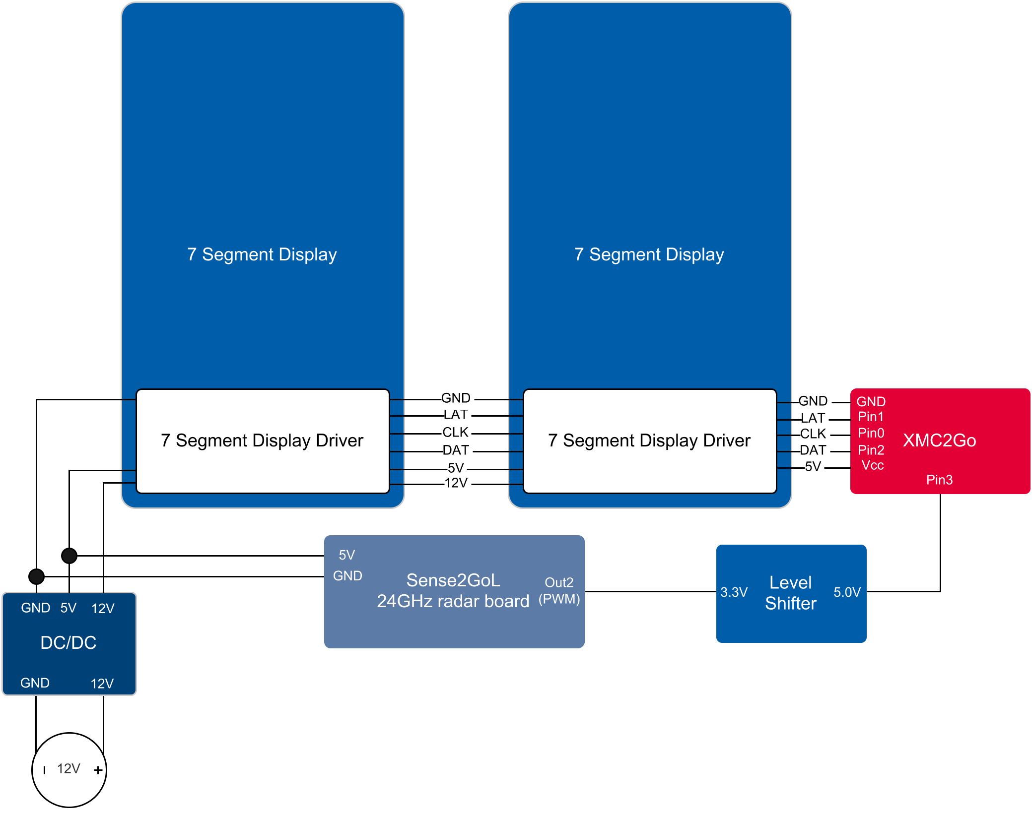
byte segmentClock = 0;
byte segmentLatch = 1;
byte segmentData = 2;

byte PWM_PIN = 3;
//-=-=-=-=-=-=-=-=-=-=-=-=-=-=-=-=-=-=-=-=-=-=-=-=

int pwm_value;

void setup()
{
  Serial.begin(9600);
  Serial.println("Large Digit Driver Example");

  pinMode(PWM_PIN, INPUT);

  pinMode(segmentClock, OUTPUT);
  pinMode(segmentData, OUTPUT);
  pinMode(segmentLatch, OUTPUT);

  digitalWrite(segmentClock, LOW);
  digitalWrite(segmentData, LOW);
  digitalWrite(segmentLatch, LOW);
}

int number = 0;

void loop()
{
  pwm_value=0;
  for (int i = 0; i <= 4; i++) {
    pwm_value += ((pulseIn(PWM_PIN, HIGH)-200));//-450)/1000;
       Serial.print("\t");
      Serial.println(pwm_value);
  }
  pwm_value = pwm_value/320/5;

  Serial.println(pwm_value);
  showNumber(pwm_value); //Test pattern
}

//Takes a number and displays 2 numbers. Displays absolute value (no negatives)
void showNumber(float value)
{
  int number = abs(value); //Remove negative signs and any decimals

  //Serial.print("number: ");
  //Serial.println(number);

  for (byte x = 0 ; x < 2 ; x++)
  {
    int remainder = number % 10;

    postNumber(remainder, false);

    number /= 10;
  }

  //Latch the current segment data
  digitalWrite(segmentLatch, LOW);
  digitalWrite(segmentLatch, HIGH); //Register moves storage register on the rising edge of RCK
}

//Given a number, or '-', shifts it out to the display
void postNumber(byte number, boolean decimal)
{
  //    -  A
  //   / / F/B
  //    -  G
  //   / / E/C
  //    -. D/DP

#define a  1<<0
#define b  1<<6
#define c  1<<5
#define d  1<<4
#define e  1<<3
#define f  1<<1
#define g  1<<2
#define dp 1<<7

  byte segments;

  switch (number)
  {
    case 1: segments = b | c; break;
    case 2: segments = a | b | d | e | g; break;
    case 3: segments = a | b | c | d | g; break;
    case 4: segments = f | g | b | c; break;
    case 5: segments = a | f | g | c | d; break;
    case 6: segments = a | f | g | e | c | d; break;
    case 7: segments = a | b | c; break;
    case 8: segments = a | b | c | d | e | f | g; break;
    case 9: segments = a | b | c | d | f | g; break;
    case 0: segments = a | b | c | d | e | f; break;
    case ' ': segments = 0; break;
    case 'c': segments = g | e | d; break;
    case '-': segments = g; break;
  }

  if (decimal) segments |= dp;

  //Clock these bits out to the drivers
  for (byte x = 0 ; x < 8 ; x++)
  {
    digitalWrite(segmentClock, LOW);
    digitalWrite(segmentData, segments & 1 << (7 - x));
    digitalWrite(segmentClock, HIGH); //Data transfers to the register on the rising edge of SRCK
  }
}


_3u05Tpwasz.png?auto=compress%2Cformat&w=40&h=40&fit=fillmax&bg=fff&dpr=2)
Comments
Please log in or sign up to comment.