


Hardware components | ||||||
 |
| × | 1 | |||
 |
| × | 1 | |||
 |
| × | 1 | |||
| × | 1 | ||||
Software apps and online services | ||||||
 |
| |||||
Hand tools and fabrication machines | ||||||
 |
| |||||
We all love servos for prototyping and building RC stuff. But most of them are fairly slow, weak and not really accurate. This project shows you how to turn a bldc into a servo motor by yourself. Creating a servo exactly matching your project needs.
Servo 101The main difference between a standard BLDC and a servo is the feedback loop.You most likely use a sensorless BLDC and therefore a complete sensorless control. Even if you use a standard sensored BLDC the angle resolution of 3x120° lacks way behind the one of a servo - because servos use a potentiometer to measure and control the output shafts position:
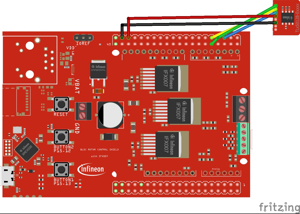
So to upgrade a BLDC motor to a servo we need to sense the position of the rotor. Instead of a potentiometer we use a XENSIV™ TLE5012B E1000 magnetic angle sensor which offers a resolution of up to 0.01° and an update rate up to 2.0 kHz.To measure the angle we place a diametral magnet at the end of our rotor. The sensor sits close to the magnet (with a small air gap of a view millimeter). This way of sensing is contactless, leads to no friction and there is no need for maintenance.To figure your magnet and mechanical setup out there is a handy simulation tool available!
In this project the motor used is a T-Motor GB54-1.
These pictures show the air gap the sensor allows as well as the motor specific setup:
To control the BLDC we use the same method as described in out post about boosting up you BLDCs torque: Torque Boost - Sensored BLDC Control (closed loop)In a nutshell: The motor spins freely while the software is creating a PWM map linked to the mechanical angle values of your rotor. This way you get a perfect matching motor control algorithm for your specific motor and sensor setup. After the mapping the control software reads the current mechanical angle value and sets the three PWM values accordingly. To turn the motor we add or subtract (depending on the direction) a phase shift value representing "90° electrical" which can be calculated by
PhaseShift = 3600/(Number_of_poles*4);using a 0.1° resolution.
Closing the loopIn a servo configuration we want to move our motor to a certain position.Therefore we measure the current position and compare it to the intended one.The difference in position (error) is then used as input signal of the control algorithm which will drive the motor to minimize the error.
A common controller for this task is a PID-controller, in our case setting the PWM duty cycle and therefore the torque of the motor.
P - proportional control: is a constant amplifier of the position difference.
control_P = error * P;I - integral control: this is a dynamic part of the controller. It grows a control value over time. It plays its role especially when small errors of the positions occur. In this case the proportional part is too small to have an significant influence. Don't let this grow to big. Therefore we constrain the value.
integrator_arm   = constrain (integrator + error,-100, 100);
control_I = integrator * I;
D - differential control: this is controlling the dynamics of the motor. So it considers the speed the position error is changing. Imagine your motor moves fast but is already close to your desired position. The Proportional control is small, the integral control might be grown. This would cause a major overshoot of the system. Therefore we introduce the differential control as negative to the others. This way it acts like a damping factor to overshooting but also slows the system down a bit.
control_D = speed * D;At the end just sum your P, I, D controls up:
//Position Control (PID)
error = intent_angle-angle;
integrator = constrain(integrator + error,-100, 100);
control = error * P + integrator * I + speed * D;
Tuning your PID values is always a bit of trail an error. My suggestion is to
- start with P until you seem to reach your desired position. If you start now with a big error (push the motor far of position) you will see overshooting
- Increase D till the overshooting goes away. This is kind of a damping factor to your system. Your motor will show way better dynamic behavior but might not reach the exact position
- Start to introduce and increase some small I and decrease P a bit
Above you can see different control settings. As you see an untuned PID controller could even show worse behavior compared to a simple P controller (I=0, D=0)
How to use the code exampeThe code works with XMC for Arduino V1.7.0 and TLE5012B library version 2.0.1
After flashing the code your motor spins uncontrolled for the first 5 seconds. Don't touch it or put any other load on it during this time.In case you motor is not spinning smoothly change the parameter
float speed_init = 0.003;This will adjust the speed of the 3 sine waves in uncontrolled mode.
Next is to adjust the offset which is depending on the mechanical setup of magnet and sensor. Set "PhaseShift" and "offset" to 0 and use + and - on the Serial monitor to change the offset till the motor stops spinning (the magnetic field is in this case directly above the mechanical field of the motor, therefore no force in introduced to spin it).
You see these parameters in the following section
//change these parameters according to motor
int offset = 53;
int PhaseShift = 130;
float speed_init = 0.003;


Comments
Please log in or sign up to comment.