


Hardware components | ||||||
 |
| × | 1 | |||
 |
| × | 1 | |||
 |
| × | 1 | |||
| × | 1 | ||||
Software apps and online services | ||||||
 |
| |||||
Hand tools and fabrication machines | ||||||
 |
| |||||
 |
| |||||
 |
| |||||
The SimpleFOC (Field Oriented Control) library implements an advanced algorithm that ensures smooth operation and a high degree of torque, velocity, and position control. Whether you are just starting out and looking for an easy and intuitive method to control your BLDC and stepper motors, or you are an advanced user wanting to delve deeper into the intricacies of the FOC algorithm to optimize your code for specific applications and hardware, this guide is for you.
By leveraging the capabilities of the IFX007T BLDC motor driver shield and the TLE5012B magnetic angle sensor, you will learn how to work with the SimpleFOClibrary for Arduino to create precise and efficient motor control systems. This guide will walk you through the setup and configuration, ensuring you have a thorough understanding of how to achieve optimal performance.
Understanding BLDC Motors and Closed-Loop ControlBLDC motors lack physical brushes to commutate the windings. Instead, they rely on electronic commutation, where the controller switches power between motor phases based on rotor position.
Open-loop control (e.g., basic PWM driving) forces the motor to follow predefined phase patterns without feedback. While simple, this approach struggles with varying loads, lacks torque precision, and risks stalling.
Closed-loop control solves these issues by continuously monitoring the rotor position and adjusting phase currents accordingly. This requires two critical components:
Angle Sensor: Measures rotor position (TLE5012B).Control Algorithm: Dynamically adjusts currents (FOC).
Why Field-Oriented Control (FOC)?Traditional control methods like trapezoidal commutation treat motor phases independently, leading to torque ripple and inefficiency. FOC takes a smarter approach:
Mathematical Transformation:FOC converts three-phase currents into a rotating two-axis system (d-q coordinates), decoupling torque generation (q-axis) from magnetic flux (d-axis).
Precision Control:By directly controlling torque and flux components, FOC minimizes losses, reduces heat, and enables smooth operation even at low speeds.
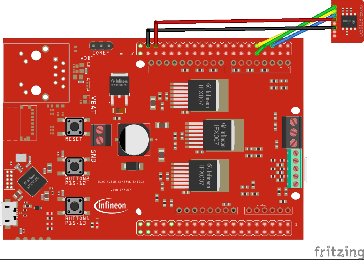
Hardware1. Stacking the IFX007T ShieldThe IFX007T motor driver shield integrates with Infineon’s XMC4700 Relax Kit or any other Arduino-compatible board. Simply stack the IFX007T shield on top of your XMC board. This provides:
- 3x PWM outputs for motor phases
- Overcurrent/thermal protection
- Up to 40V motor supply compatibility
Note: For non-XMC boards (e.g., Arduino Uno), wire the IFX007T’s PWM pins (U/V/W) and enable pins (EN_U/EN_V/EN_W) manually.
2. Connecting the TLE5012B Angle SensorThe TLE5012B’s 3-wire SPI interface simplifies integration:
CS (Chip Select): Connect to a GPIO pin.SCK/MISO/MOSI: Link to the board’s dedicated SPI pins (see schematic).
Critical Step: Mount the sensor’s magnet concentric to the motor shaft. Even a 1mm misalignment can degrade accuracy.
1. Getstarted with Arduino IDE and XMC Boards
To start programming with XMC boards, you need to set up the Arduino IDE. Follow our step-by-step guide to get started with XMC for Arduino: documentation.
Get Started!
With everything prepared we’re ready to flash the first code example to the microcontroller. In order to do that you have to do the following steps in the Arduino IDE:
1.Select the right board
Once you have installed the XMC board family, you can select one of the supported boards from the menu: Tools > Board > Infineon’s XMC Microcontroller. In our case we have to choose the XMC4700 Relax Kit in order to select the correct board.
The TLE5012 is a magnetic angular sensor that communicates over SPI. It provides precise angle measurements, which are essential for motor control applications. To use it with SimpleFOC, we need to create a custom sensor class that extends the Sensor base class provided by SimpleFOC.
We create a custom classTLE5012Sensor that extends the Sensor class. This class will handle the initialization and angle reading from the TLE5012 sensor.
The TLE5012Sensor class has:
- A constructor to initialize the sensor with SPI pins.
- An
init()method to initialize the sensor hardware. - A
getSensorAngle()method to read the angle in radians.
In the setup() function, we initialize the TLE5012 sensor by calling the init() method of the TLE5012Sensor class. This sets up the SPI communication and ensures the sensor is ready to provide data.
void setup() {
    Serial.begin(115200);
    while (!Serial); // Wait for the serial port to connect (for debugging)
    // Initialize the TLE5012 sensor
    tle5012Sensor.init();
    Serial.println("Setup complete. Starting sensor loop...");
}
In the loop() function, we continuously read the sensor angle and velocity using the update(), getAngle(), and getVelocity() methods provided by the Sensor class. These values are printed to Arduino's Serial Monitor for debugging.
void loop() {
    // Update the sensor
    tle5012Sensor.update();
    // Get the angle and print it
    float angle = tle5012Sensor.getAngle();
    float velocity = tle5012Sensor.getVelocity();
    Serial.print("Angle (rad): ");
    Serial.print(angle);
    Serial.print("\tVelocity (rad/s): ");
    Serial.println(velocity);
    delay(100); // Small delay to avoid flooding the serial monitor
}
The TLE5012 sensor provides the angle in degrees. We convert this to radians because SimpleFOC uses radians for angle calculations. The conversion formula is:
float angleRad = (angle + 180.0) * (M_PI / 180.0);
float TLE5012Sensor::getSensorAngle() {
    double angle = 0.0;
    _sensor.getAngleValue(angle); // Read the angle from the sensor
    // Convert the angle to radians and adjust it to the range [0, 2π]
    float angleRad = (angle + 180.0) * (M_PI / 180.0); // Convert degrees to radians
    if (angleRad > 2 * M_PI) {
        angleRad -= 2 * M_PI; // Ensure the angle is within 0 to 2π
    }
    return angleRad;
}
During initialization, we check for errors and print them to the Serial Monitor if any occur. This helps in debugging hardware or communication issues.
void TLE5012Sensor::init() {
    _checkError = _sensor.begin();
    if (_checkError != NO_ERROR) {
        Serial.print("TLE5012 sensor initialization error: ");
        Serial.println(_checkError, HEX);
    } else {
        Serial.println("TLE5012 sensor initialized successfully!");
    }
}
Upload the code to your XMC4700 and open the Serial Monitor (set to 115200 baud). You should see the angle and velocity values printed every 100ms. This confirms that the sensor is working correctly.
Setup complete. Starting sensor loop...
Angle (rad): 1.57    Velocity (rad/s): 0.00
Angle (rad): 3.14    Velocity (rad/s): 0.10
Angle (rad): 4.71    Velocity (rad/s): 0.05
By following these steps and using the provided code, you can successfully integrate the TLE5012 sensor with the SimpleFOC library!
#include <SimpleFOC.h>
BLDCMotor motor = BLDCMotor(4, 0.73);- This creates an instance of the
BLDCMotorclass.
The constructor parameters are:
polepairs: The number of pole pairs in the motor (here: 4).
R: The phase resistance of the motor in Ohms (here: 0.73 Ohms).
const int U = 11;
const int V = 10;
const int W = 9;
const int EN_U = 6;
const int EN_V = 5;
const int EN_W = 3;

BLDCDriver3PWM driver = BLDCDriver3PWM(U, V, W,EN_U,EN_V,EN_W);- These lines define the pins used for the motor phases (U, V, W) and enable pins (EN_U, EN_V, EN_W).
- An instance of
BLDCDriver3PWMis created, which controls the motor using three PWM signals.
float target_position = 0;

Commander command = Commander(Serial);
void doTarget(char* cmd) { command.scalar(&target_position, cmd); }
void doLimit(char* cmd) { command.scalar(&motor.voltage_limit, cmd); }
void doVelocity(char* cmd) { command.scalar(&motor.velocity_limit, cmd); }target_positionis a float variable that holds the target position for the motor in radians.Commanderis used for serial communication to allow setting parameters like target position, voltage limit, and velocity limit through serial commands.
void setup() {


  Serial.begin(115200);
  SimpleFOCDebug::enable(&Serial);

  driver.voltage_power_supply = 12;
  driver.voltage_limit = 6;
  if(!driver.init()){
    Serial.println("Driver init failed!");
    return;
  }
  motor.linkDriver(&driver);

  motor.voltage_limit = 3;
  motor.velocity_limit = 5;
  motor.controller = MotionControlType::angle_openloop;

  if(!motor.init()){
    Serial.println("Motor init failed!");
    return;
  }

  command.add('T', doTarget, "target angle");
  command.add('L', doLimit, "voltage limit");
  command.add('V', doLimit, "movement velocity");

  Serial.println("Motor ready!");
  Serial.println("Set target position [rad]");
  _delay(1000);
}- The
setupfunction initializes the pins, serial communication, and motor driver. - It sets the power supply voltage (
driver.voltage_power_supply) to 12V and limits the driver voltage to 6V. - The motor's voltage limit is set to 3V, and velocity limit to 5 rad/s.
- The motion control type is set to
angle_openloop, which means the motor will operate in open-loop control, where the angle is controlled without feedback. - The
Commanderis configured to allow serial commands for setting the target angle, voltage limit, and velocity limit.
void loop() {
  motor.move(target_position);
  command.run();
}- The
loopfunction continuously moves the motor to thetarget_positionusing open-loop control. - The
command.run()allows for real-time adjustments of the motor parameters through serial commands.
The TLE5012 sensor provides real-time angle feedback to the motor controller. Closed-loop control: The motor uses the sensor feedback to accurately reach the target angle. Serial Commands: You can set the target angle using the serial monitor by sending the T command followed by the desired angle in radians.
#include <SimpleFOC.h>
#include "TLE5012Sensor.h"
#define PIN_SPI1_SS0   36  // Chip Select (CS)
#define PIN_SPI1_MOSI  37  // MOSI pin
#define PIN_SPI1_MISO  63  // MISO pin
#define PIN_SPI1_SCK   38  // SCK pin
These pins are used for SPI communication with the TLE5012 sensor.
tle5012::SPIClass3W tle5012::SPI3W1(1);  // SPI port 1
TLE5012Sensor tle5012Sensor(&SPI3W1, PIN_SPI1_SS0, PIN_SPI1_MISO, PIN_SPI1_MOSI, PIN_SPI1_SCK);
The TLE5012Sensor object is initialized with the SPI pins.
BLDCMotor motor = BLDCMotor(4, 0.73);  // 4 pole pairs, 0.73 Ω phase resistance
BLDCDriver3PWM driver = BLDCDriver3PWM(U, V, W,EN_U,EN_V,EN_W);  // PWM pins and enable pin
The BLDCMotor object represents the motor, and the BLDCDriver3PWM object controls the motor using PWM signals.
float target_angle = 0;  // Target angle in radians
Commander command = Commander(Serial);  // Serial command interface
void doTarget(char* cmd) { command.scalar(&target_angle, cmd); }
The target_angle variable stores the desired motor positionThe Commander class allows setting the target angle via the Serial Monitor
void setup() {


  // Initialize serial communication
  Serial.begin(115200);
  while (!Serial);  // Wait for the serial port to connect
  SimpleFOCDebug::enable(&Serial);  // Enable debugging output

  // Initialize the TLE5012 sensor
  tle5012Sensor.init();
  motor.linkSensor(&tle5012Sensor);  // Link the sensor to the motor

  // Driver configuration
  driver.voltage_power_supply = 12;  // 12V power supply
  driver.voltage_limit = 6;  // Driver voltage limit (50% of power supply)
  if (!driver.init()) {
    Serial.println("Driver init failed!");
    return;
  }

  // Link the motor and the driver
  motor.linkDriver(&driver);

  // Set FOC modulation type
  motor.foc_modulation = FOCModulationType::SpaceVectorPWM;

  // Set motion control type
  motor.controller = MotionControlType::angle;  // Closed-loop position control

  // Controller tuning
  motor.PID_velocity.P = 0.2f;  // Proportional gain for velocity control
  motor.PID_velocity.I = 20;    // Integral gain for velocity control
  motor.PID_velocity.D = 0;     // Derivative gain for velocity control
  motor.voltage_limit = 3;      // Voltage limit to avoid overheating
  motor.LPF_velocity.Tf = 0.01f;  // Low-pass filter for velocity
  motor.P_angle.P = 20;         // Proportional gain for angle control
  motor.velocity_limit = 5;     // Velocity limit (5 rad/s ~ 50 RPM)

  // Initialize motor and start FOC
  motor.init();
  motor.initFOC();

  // Add target command to the commander
  command.add('T', doTarget, "target angle");

  Serial.println(F("Motor ready."));
  Serial.println(F("Set the target angle using serial terminal:"));
  _delay(1000);
}
The setup() function initializes the motor, sensor, and driver, and configures the control parameter.
void loop() {
tle5012Sensor.update();
  // Main FOC algorithm function
  motor.loopFOC();

  // Motion control function
  motor.move(target_angle);

  // User communication
  command.run();
}
The loop() function continuously runs the FOC algorithm and updates the motor's position based on the target angle.
By combining the XMC4700’s, the IFX007T’s robust driving, and the TLE5012B’s precision sensing, you’ve created a very capable motor control system. Simple FOC abstracts the complex math, letting you focus on application logic whether you’re building a CNC machine, robotic arm, or autonomous drone.
Links:
https://docs.simplefoc.com/code
Attribution : https://www.vecteezy.com/free-photos/electric-motor


Comments