

Hardware components | ||||||
 |
| × | 1 | |||
 |
| × | 1 | |||
 |
| × | 1 | |||
 |
| × | 1 | |||
Software apps and online services | ||||||
 |
| |||||
Hand tools and fabrication machines | ||||||
 |
| |||||
 |
| |||||
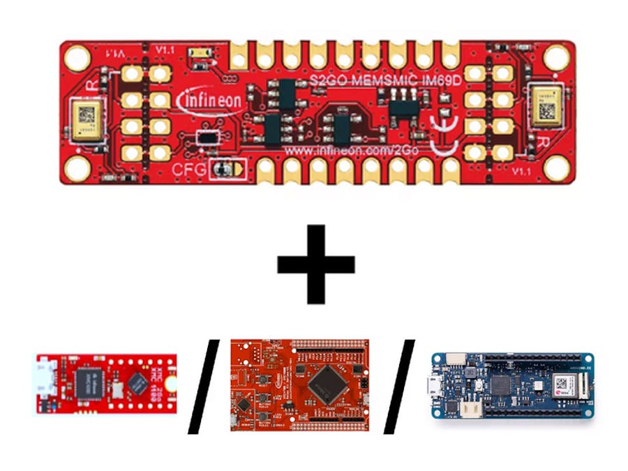
This article describes how to interface the IM69D130 stereo mircophone Shield2Go with the Arduino MKR WiFi 1010 and two of Infineons microcontroller boards enabled for the Arduino IDE, the XMC4700 Relax Lite Kit and the XMC2Go. Later, this project describes how to use the I2S.h library to receive audio data from the microphone.
1. Setting up the HardwareBelow you can find pinouts and connections to interface the MEMS microphone Shield2Go with- 1.1 Arduino MKR WiFi 1010- 1.2 XMC4700 Relax Kit- 1.3 XMC2Gocontroller boards.
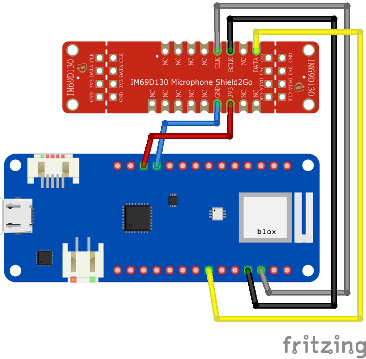
1.1. Arduino MKR WiFi 1010 - I2S MEMS Microphone IM69D130The connection between Arduino and the microphone can be established by using jumper cables and the following configuration:
Microphone - Arduino MKR WiFi 1010
- 3V3 - 3V3 [red]
- GND - GND [blue]
- BCLK - Pin2 (SCK) [black]
- DATA - PinA6 (SD) [yellow]
- WCLK - Pin3 (FS/WS) [grey]
The easiest way of interfacing the microphone with the XMC4700 is by using the My IoT Adapter. This adapter can be directly connected to the XMC4700. To use the microphone plug it into the first socket of the adapter board, so that it looks like in the picture below.
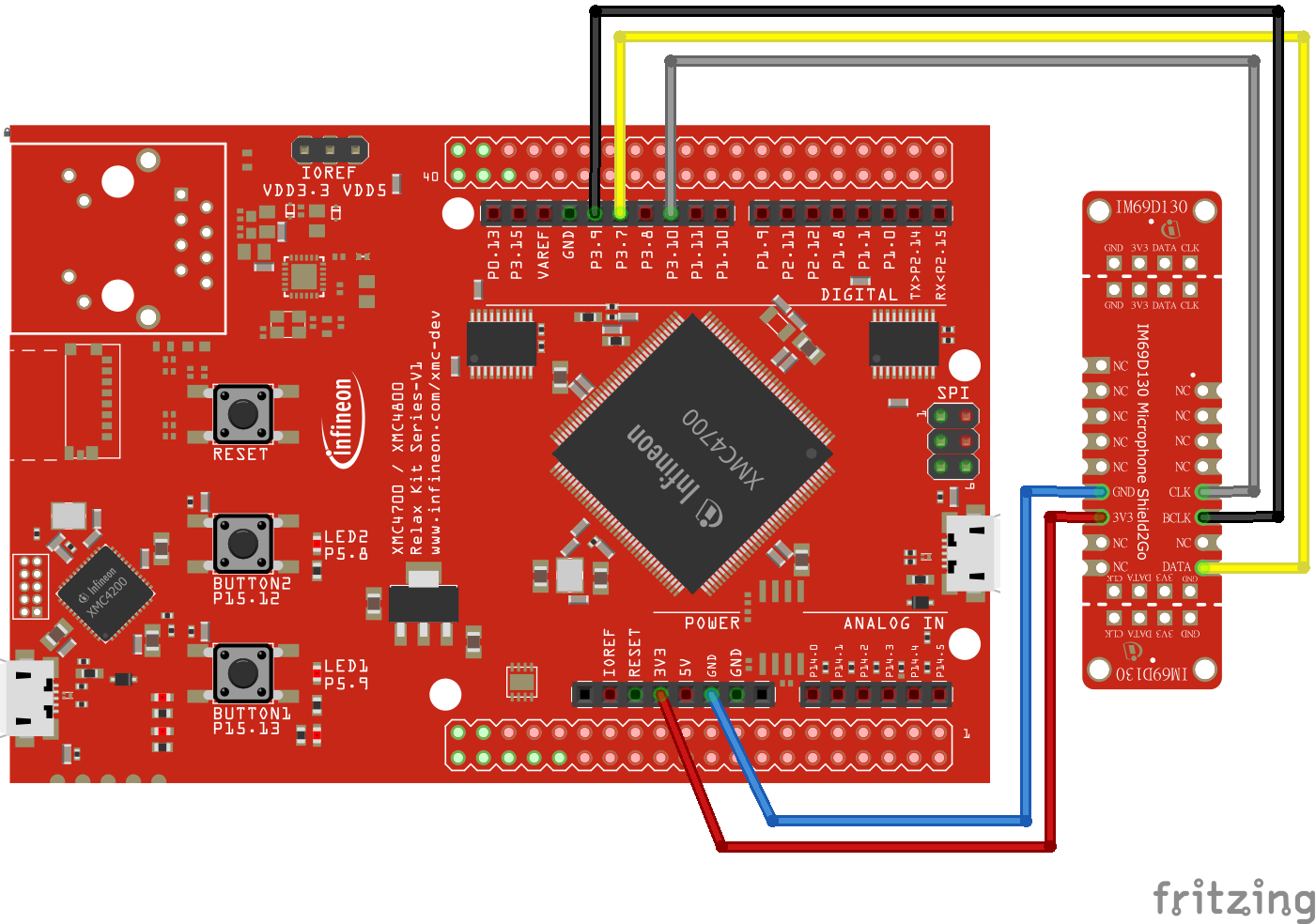
If you don't own a MyIoTAdapter, fear not, because it is also possible to wire it up.We would only need the XMC4700 Lite Kit and some wires. The connections are to be assembled as follows :
Microphone - XMC4700 Lite Kit
- 3V3 - 3V3 [red]
- GND - GND [blue]
- BCLK - Pin3.9 (SPI:SCK) [black]
- DATA - Pin3.7 (SPI:MISO) [yellow]
- WCLK - Pin3.10 (SPI:SS) [grey]
This one is the smallest from all presented configurations. The XMC2Go is built to fit the layout of a Shield2Go therefore it is not necessary to use jumper cables to connect the microphone to the XMC2Go board. The easiest way is to solder male headers to one of the boards and female headers to the other board and then to just connect them like shown into the picture. (We used female headers on the XMC2Go and male headers for the microphone.)
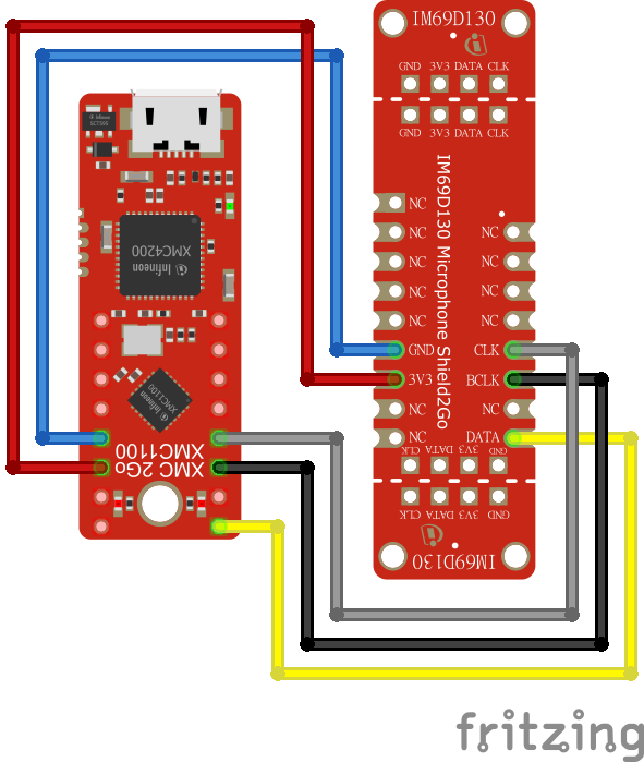
It is also possible to do a wired connection from the XMC2Go to the microphone, but it is not recommended because all wired connections potentially lead to errors within the I2S connection. If you still want a wired connection do it like this:
Microphone - XMC2Go
- 3V3 - VSS [red]
- GND - VDD [blue]
- BCLK - Pin0.8 (SPI:SCK) [black]
- DATA - Pin0.6 (SPI:MISO) [yellow]
- WCLK - Pin0.9 (SPI:SS) [grey]
At first we need a functioning Arduino IDE installation which you can get here.
2.1. Arduino MKR WiFi 1010After the installation of the IDE we have to add the board into the board manager. Therefore click Tools menu -> Boards -> Boards Manager and install the Arduino SAMD Boards (32-bits ARM Cortex-M0+). To do so click so for that in the Boards Manager, select the newest version and click install.
Afterwards we are now ready to create our first sketch to use the IM69D130 MEMS Microphone Shield2Go.
For further information on how to get started look here.
Starting with the code:
Lets have a quick look into the Arduino sketch. The basic functionality of this sketch is to read audio data from the microphone and process it to show the sound pressure level through the serial plotter provided by the Arduino IDE.
At first we have to include the I2S.h library to be able to communicate with the microphone.
#include <I2S.h>After that we have to do the setup for the Arduino.In order to display the output from the microphone in the serial monitor, we have to set a serial connection. Additionally, we have to establish the I2S connection by using the libraries begin function.
void setup() {
  // Open serial communications and wait for port to open:
  // A baud rate of 115200 is used instead of 9600 for a faster data rate
  // on non-native USB ports
  Serial.begin(115200);
  while (!Serial) {
    ; // wait for serial port to connect. Needed for native USB port only
  }

  // start I2S at 16 kHz with 32-bits per sample
  if (!I2S.begin(I2S_PHILIPS_MODE, 16000, 32)) {
    Serial.println("Failed to initialize I2S!");
    while (1); // do nothing
  }
}
Within the loop function we set an array of integer variables. Then we check for the availability of I2S data on the microphone. Afterwards the I2S values get read out from the I2S buffer and saved into our integer array. The mean value of the samples array is calculated; to normalize the output we substract the mean value from every iteration of the samples. Then we compute the minimum and the maximum values of the samples. Finally we print out the the difference between them to display a basic pressure level. You can find the whole code attached at the end.
void loop() {
  // read a bunch of samples:
  int samples[SAMPLES];

  for (int i=0; i<SAMPLES; i++) {
    int sample = 0;
    while ((sample == 0) || (sample == -1) ) {
      sample = I2S.read();
    }
    // convert to 18 bit signed
    sample >>= 14;
    samples[i] = sample;
  }

  // ok we hvae the samples, get the mean (avg)
  float meanval = 0;
  for (int i=0; i<SAMPLES; i++) {
    meanval += samples[i];
  }
  meanval /= SAMPLES;

  // subtract it from all samples to get a 'normalized' output
  for (int i=0; i<SAMPLES; i++) {
    samples[i] -= meanval;
    //Serial.println(samples[i]);
  }

  // find the 'peak to peak' max
  float maxsample, minsample;
  minsample = 100000;
  maxsample = -100000;
  for (int i=0; i<SAMPLES; i++) {
    minsample = min(minsample, samples[i]);
    maxsample = max(maxsample, samples[i]);
  }
  Serial.println(maxsample - minsample);
}Now we will have a look into the configuration of the XMC4700 Relax Lite Kit and the XMC2Go.
Here we assume you have a working Arduino IDE with the finished integration of the XMC libraries into the Arduino IDE. If this is not the case, click here for the implementation guide.
Everything should be set up now, so we can take a look into the code. The basic functionality of this code is to read audio data from the microphone and process it, to show the sound pressure level through the serial plotter provided by the Arduino IDE.
Starting with the code:
At first we have to include the I2S.h library to be able to communicate with the microphone.
#include <I2S.h>o be able to display the output from the microphone in the serial monitor we have to set the serial connection. Then we have to establish the I2S connection by using the libraries begin function.
Before that we also disable both microphones and enable only one of them so that the signal won't get distorted.
void setup()
{
    // Open serial communication with a baudrate of 115200
    Serial.begin(115200);
    // Wait until the serial port is connected
    while (!Serial);

    I2S.disableMicrophones();
    // Enable the microphone when word select is high
    I2S.enableMicrophoneHigh();

    // Start I2S at 11 kHz with 16 bits per sample
    if (I2S.begin(I2S_PHILIPS_MODE, 11000, 16) != 0)
    {
        Serial.println("Failed to initialize I2S!");
        // Do nothing and wait
        while (true);
    }
}
The loop function looks as follows. At first we create a samples array with 128 entries. When there are 128 samples or more saved in the buffer then we read the values and save them into our previously created array. Then the mean value is calculated and gets substracted from all samples to normalize the output. Afterwards the minimal und maximal samples are calculated and then printed out into the serial plotter. You can find the whole code attached at the end.
void loop()
{
    // Array to store the samples
    int32_t samples[128];
    if (I2S.available() > 128)
    {
        // Read 128 samples into the array
        I2S.read(samples, 128);

        float meanValue = 0;
        for (int i = 0; i < 128; i++)
        {
            meanValue += samples[i];
        }
        meanValue /= 128;

        // Substract it from all samples to normalize output
        for (int i = 0; i < 128; i++)
        {
            samples[i] -= meanValue;
        }

        // Get the peak to peak maximum
        float maxSample, minSample;
        minSample = 100000;
        maxSample = -100000;
        for (int i = 0; i < 128; i++)
        {
            minSample = min(minSample, samples[i]);
            maxSample = max(maxSample, samples[i]);
        }
        Serial.println(maxSample - minSample);
    }
}To access the plotter go to Tools -> Serial Plotter. It is necessary to have the same baud rate selected that we have set within the code. The baud rate can be selected at the bottom left corner of the Serial Plotter. In our case its 115200 Baud for Arduino MKR Wifi 1010 and 1000000 Baud for the XMC4700 Relax Lite Kit and the XMC2Go. If you have problems with the output not showing of properly you can always try to tickle around with baud rate, frequency and bit per sample.
When looking into the output of the serial plotter it could look like this:
In this picture we can see the Arduino IDE Plotter while we play the intro of a song. The plotter shows the rise of the overall song volume with the high peaks being the songs beats.To be able to see big spikes of your sound level you can snap fingers or knock on your table.
If you get a constant blurry plot with no noticeable spikes that are cause by your knocking or snapping, then there might be a failure on your data line connection. To solve this issue try do establish shorter cables, solder the contacts or use shielded cables to be sure nothing interferes the data connection.
4. Further Reading and more examplesWe hope you were able to follow all the examples and code snippets we provide here. If you are interested in more examples and use cases for the IM69D130 MEMS Microphone Shield2Go you can look into its GitHub repository.
If you want to know, how to use this shield together with a Raspberry-Pi, have a look at our other hackster.io article on that topic.
Furthermore if you want to use the microphone for a Machine Learning project via Edge Impulse you can take a look at this hackster.io article.


Comments