


Hardware components | ||||||
 |
| × | 1 | |||
Software apps and online services | ||||||
| ||||||
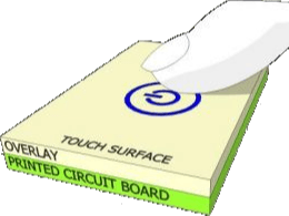
Capacitive touch sensing has replaced more than billions of mechanical buttons, but not only buttons, it enables hundreds of diverse types of sensing applications.
The CY8CKIT-041-41XX PSoC™ 4100S CapSense Pioneer Kit enables you to evaluate and develop with Infineon's fourth-generation, low-power CAPSENSE™ solution.
Out of the box, the preinstalled firmware
The preinstalled firmware demonstrates some touch functionality as described in the code example CE214025 Trackpad With Color Gamut.
Running the code examples allows to change the color of the RGB-LED by touching on the RGB-rainbow label attached to the black box. The brightness can be controlled by two touch buttons.
Getting started with PSoC Creator and CY8CKIT-041-41XXPSoC Creator is the general IDE to be used for Infineon's (formerly Cypress') PSoC microcontroller.
Note 1: Infineon has already released a newer IDE, called ModusToolbox, but it does not support older PSoC devices and kits, like CY8CKIT-041-41XX. Remember, ModusToolbox shall be used for the latest PSoC6 family and also for newer PSoC4 devices.
In the following it is expected that the complete PSoC Creator installation has been done already on your computer before we continue from here.
It is further recommended to install the related development tools respectively kit support package e.g. CY8CKIT-041-41XX -> DesignSupport -> Development Tools -> DOWNLOAD - CY8CKIT04141XXSetup_RevSA.exe
Inside the installation folder, e.g. C:\Program Files (x86)\Cypress\CY8CKIT-041-41XX PSoC 4100S Pioneer Kit\ all details like documentation, hardware information, and software can be found.
The preinstalled firmware demonstrates the touch functionality as described in the code example CE214025 Trackpad With Color Gamut.
Open PSoC Creator and open the project wizard (Menu: File -> New -> Project...) and choose the [ target kit CY8CKIT-041-41XX (PSoC4100S) ]. In the next window choose [ code example ] and filter for CE214025 and select [ CE214025 Trackpad With Color Gamut ]. Next, and you can define the location and change project name on your personal requirements before you finish to start the project creation.
As the code example was developed using an older version of PSoC Creator, an error might be reported regarding outdated components. In this case a component update should be forced by Menu: Projects -> Update Components (actual project name)
Finally, your PSoC creator should look like this.
The PSoC Creator User Guide helps to understand and navigate that IDE, but in short words:
- The Left column shows the project tree.
- The center window shows the opened files (using tabs, to keep files open).
- The right column lists available PSoC device components.
- The bottom window shows output results, and messages.
Connect the kit with the Micro-USB cable and [ Program ] the project. In case no programmer (KitProg) is found and/or an update is required then you need to open (see windows start menu) the external tool PSoC Programmer -> Utilities -> Upgrade Firmware.
After fixing these historical version issues, you will surely be able to re-program the preinstalled firmware respectively code example and observe the LED color change and brightness when touching the rainbow matrix or buttons.
While the kit includes a plastic enclosure that enables you to use the kit as a finished product that implements a USB or a Bluetooth Mouse the following article explains how 'hack the kit' and how to use Infineon's CapSense technology in your own Maker-project. It gives you some ideas of applications, and how to implement it. Let's open the kit...
Two CapSense touch buttons, a 7x7 trackpad, and a proximity sensor are designed using a Flex PCB. The CapSense Design Guide gives a lot of very detailed information including hardware consideration and software implementation.
In order to understand and modify the existing code example, let's do a copy of the existing code example.
Note: Inside PSoC Creator you can replicate a project by copy & paste (right/left mouse-click on the project within the project tree). The new name, automatically generated with extension '_Copy_01' can easily be renamed by a right-mouse-click 'Rename (F2)'
Looking to the project, CE214025, a double-click on the CapSense component to see the current configuration.
As described before, the code example has implemented two buttons and a 7x7 matrix for the trackpad. A manual tuning is selected. You can open the component Datasheet to get more information especially also about the API software interface to address the CapSense feature by software. For the moment, let's forget about further details, or keep in mind to read about it in the CapSense Datasheet and/or CapSense Design Guide.
Depending on the PSoC family a different CapSense version may be implemented, that can vary in features, and (slightly) software API.
Looking to the main.c source file we can identify some basic API calls as follows:
CapSense_Start();to initialize the CapSense block
CapSense_InitializeWidgetBaseline(ID);to initialize the baseline of an individual sensor field. This should be done for all sensors. Alternatively CapSense_InitializeAllBaselines(), can be used for all at once.
That's all for the overall initialization.
Inside the program loop the CapSense activity has to be observed, a scan is started and data is processed when available, meaning when CapSense is not busy, a new scan is initiated, and when done the sensor data is retrieved. Unfortunately, the given code example has encapsulated this handling into a state machine, what makes it a little unclear on the first view.
The CapSense Design Guide gives a more clear picture in Code Listing 1 of what to do:
/* Initialize CapSense component */
CapSense_Start();

/* Scan all widgets */
CapSense_ScanAllWidgets();
for(;;)
{
    /* Do this only when a scan is done */
    if(CapSense_NOT_BUSY == CapSense_IsBusy())
    {
        /* Process all widgets */
        CapSense_ProcessAllWidgets();

        /* Scan result verification */
        if (CapSense_IsAnyWidgetActive())
        {
            /* Add any required functionality  based on scanning result */
        }

        /* Start next scan */
        CapSense_ScanAllWidgets();
    }
}For our first steps with CapSense let's remove the Flex PCB and start to make a first experiment.
- Solder a coin (or any other metal plate) to e.g. J4-pin8 (0.2)
- PSoC Creator: File -> New -> Project... Target kit: CY8CKIT-041-41XX -> Empty Schematic
- Drag & Drop the CapSense component into your schematic
- Open the configuration GUI by double-click the CapSense component
- Add one button (e.g. Button0)
- Optional: Rename the name (Capsense), that makes it easier typing your software
- Ensure SmartSense (Full Auto-Tune) is selected
- Ok to close the configuration window
- Drag & Drop [ Ports and Pins ] -> Digital Output Pin into your schematicWe will later control this pin (connected to LED) by our touch button.
- Open the configuration GUI by double-click the Output component
- Define a name (e.g. LED)
- Uncheck the HW connection, as this we will control the port by software
- Initial (default) state shall be high, as the LED on the kit will be switched-on by low-level (see details in the kit schematic of CY8CKIT-041-41XX)
- Ok to close the configuration window
So far, the basic setup was done for our first experiment: We have one CapSense button and one Port to control a LED.
Of course, we need to define the external pins. This is done by the pin mapping that you can open in your project tree -> Design Wide Resources -> Pins
- CapSense requires a reference capacitor (CMOD), available on the kit, P4.2
- The red LED is on board connected to P3.4
- (see above) we have connected our coin to P0.2
Now it is time to generate and add the required libraries (e.g. CapSense, GPIO) what is initiated as followed:
- PSoC Creator: Build -> Generate Application
You will find the subfolder [ Generated_Source ] inside the project tree.
Now open main.c and add the code from the CapSense Design Guide, remember to keep the names of the peripherals (CapSense, LED, etc.) which will be used always as prefix for each API call.
#include "project.h"

int main(void)
{
    CyGlobalIntEnable; /* Enable global interrupts. */

    CapSense_Start();
    CapSense_InitializeAllBaselines();

    for(;;)
    {
        /* Do this only when a scan is done */
        if(CapSense_NOT_BUSY == CapSense_IsBusy())
        {
            /* Process all widgets */
            CapSense_ProcessAllWidgets();

            /* Scan result verification */
            /* Add any required functionality  based on scanning result */

            if (CapSense_IsWidgetActive(CapSense_BUTTON0_WDGT_ID))
            {
                LED_Write(0);    // LED on
            }
            else
            {
                LED_Write(1);    // LED off
            }

            /* Start next scan */
            CapSense_ScanAllWidgets();
        }
    }
}

/* [] END OF FILE */
If you finished your application code just [ Build ] and [ Program ] it to the board.
Now, each time you touch the coin the red LED will light. Does it work?
But as CapSense reacts on changes of capacity, it works also 'through' glass...
or cardboard...
or wood, plastic, or... basically any not inductive material.
That's the time when you can play around now. Congratulation! Your first CapSense project works!
CapSense - TunerThe previous example has used the full-auto-tune mode, that means the CapSense firmware try to identify automatically between a touch and non-touched element. Honestly, this works very well for many scenarios. However, the user can observe the real CapSense signal and adjust the settings/limits.
For that the CapSense-Tuner can be included to the project, that communicates the data via the on-board I2C/USB bridge to the PC-GUI
For this we need the following enhancement done in our project:
- Add the [ Communications ] -> [ I2C ] -> EZI2C Slave (SCB) component
- Configure the EZI2C: 100kbps, Slave-address: 0x08 and 16bits
- Pin mapping: EZI2C:scl -> P3.0, EZI2C:sda -> P3.1
- Modification of
main.c
int main(void)
{

    /* Start EZI2C component */
    EZI2C_Start();
    EZI2C_EzI2CSetBuffer1(sizeof(CapSense_dsRam),
                          sizeof(CapSense_dsRam),
                          (uint8 *)&CapSense_dsRam);

    CapSense_Start();

    ...

    for(;;)
    {
        /* Process all widgets */
        CapSense_ProcessAllWidgets();

        /* Include Tuner */
        CapSense_RunTuner();

        ...

    }
}- Compile, Build & Program!
- PSoC Creator: [ Tools ] -> [ Component Tuners ] -> Select your project
When the Sense Tuner opens automatically the project's CapSense component configuration is read and the implemented buttons, sliders, etc. are shown.
- Sense Tuner [ Tools ] -> [ Tuners Communication Setup... / F10 ] -> Adjust the settings regarding the project's EZI2C configuration
- Press okay
- Connect (what, if successful, will enable the Start button)
- Enable by the checkbox the sensor element (e.g. Button0_Sns0)
- Start the communication
- Touch the button while observing the Touch Signal Graph. when the signal is strong enough the button will change its color from green to red, and becomes green, when it is not touched anymore and the signal falls below the threshold limit.
While we have used the Smart-Sense (Full Auto-Tune), what works in many cases pretty well, special CapSense designs may require to set individual parameters or a complete manual tuning, what is also possible with CapSense and the presented tools.
Again, keep in mind to read about it in the CapSense Datasheet and/or CapSense Design Guide about the details and further explanation of the shown data, parameters and CapSense calibration.
CapSense OutlookWell, so far, a quick demonstration of the basic steps how to make your first CapSense button project.
Several CapSense project examples and ideas can be found on Hackster.io, that give more hints.
And don't forget to visit the Infineon Community to connect and network with engineers across the globe. Get help from Infineon support engineers, and expert members to solve your design challenges anytime, from anywhere, in any topic.
Keen to see YOUR FIRST CapSense PROJECT ;-)


Comments
Please log in or sign up to comment.