


Hardware components | ||||||
 |
| × | 1 | |||
 |
| × | 1 | |||
 |
| × | 1 | |||
Software apps and online services | ||||||
 |
| |||||
Therarduino a belt that helps us in social distancing, as you can guess from the name this project is inspired by the Theremin project. The theremin is an electronic musical instrument, the oldest known that does not involve physical contact of the performer with the instrument.The sound was generated by exploiting the beats produced by two high frequency oscillators (300 khz), and was sent to a filter pass low. So after having suppressed all the high-pitched components, the sound was amplified and spread through the loudspeaker.
But how does the Theremin work?
If you mix the signals from two RF (Radio Frequency) oscillators together, you will get different frequencies at the output.
The most important frequencies for the construction of sound are the sum and the difference obtained from the frequencies of the mixed oscillators (The principle whereby mixing two signals produces a third signal is called heterodyning).
Moving your hand near the antenna changes the frequency of an LC oscillator.
In an LC oscillator, the frequency is determined by the value of an inductance (L), and by the value of a capacitor (C).
If you connect an antenna to the capacitor, the antenna will function as an extra charge to the capacitor, and thus will vary the frequency of the oscillator.
Moving your hands around the antenna will therefore vary the capacitance of the capacitor, and with it the frequency of the oscillator.
However, these changes are very small, less than one percent.
If the oscillator is 1 KHZ, the frequency variation will only be 10 HZ. Instead with a 500 KHZ oscillator the 1% variation is 5000 Hertz.
So my idea was to take a cue from the Theremin project and use a copper toroidal antenna, which will act as a belt and an arduino BLE to read the output signal from the PCB (self-built) and make a piezo sound.
the pcb with all the connections was designed and various tests were carried out with aruduino to read the signal
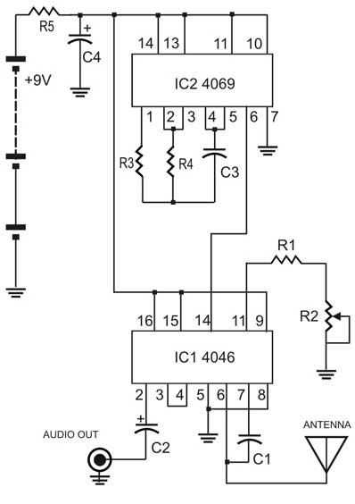
Technical explanation and wiring diagram
For the realization of the two oscillators two integrated circuits were used, a hex inverter (IC2 - 4069) and a PLL (IC1 - 4046).
The 4069 IC2 is the Theremin's fixed oscillator.
The CD 4069 (IC2) device consists of six CMOS (Complimentary Symmetry Metal Oxide emiconductor) inverter circuits, typically used in digital circuits to perform a logic function called "inversion".
Each IC contains six identical sections; hence the term "hexadecimal inverter".
The 4069 is normally used to invert the signals placed at its input, and by applying a small RC circuit to its inputs we obtain a fixed frequency oscillator.
The fixed oscillator output frequency is around 70 KHz
When the Theremin does not produce sound, with the hand farthest from the antenna, it means that the frequency of the fixed oscillator is equal to the frequency of the variable oscillator.
Under these conditions, the phase relationship of the two oscillators will be constant due to their small but finite capacitive coupling, so no audible sound will be produced.
The section around the PLL 4046 (IC1) forms the Theremin's variable oscillator.
Most of the Theremin circuits made with discrete components that you find on the internet are usually based on two oscillators both made with the CD 4096 or similar in an RC circuit, where the calibration of the variable oscillator frequency is done via a trimmer and potentiometer for the 0.
Given the very high frequencies involved, using two RC oscillators it becomes very difficult to calibrate the variable oscillator.
As soon as your hand approaches the circuit it begins to self-oscillate
The potentiometer is used to make the perfect coupling calibration between the frequencies of the two oscillators and must be adjusted so that no sound from the Theremin is produced without bringing your hand close to the antenna.
When the circuit is calibrated and does not produce sounds without bringing the hand close to the antenna, it indicates that the frequencies produced by the two oscillators are the same.
Moving your hand around the antenna changes the capacity of the VCO control capacitor and therefore its output frequency.
The frequencies generated by the oscillators are directly connected with the supply voltage, so by varying the supply voltage the frequencies emitted by the oscillators will change.
The two integrated oscillators can be powered up to 20 V, changing the values of the resistors and capacitors can be powered at the desired voltage.
The circuit draws less than 2 mA of current so with a 9V battery you can have fun for days and days.
The project is still "WORK IN PROGRESS" you have to work a lot on the calibration to have a social distance of at least 150cm.
I hope you liked the idea, I tried to do something different, experimenting with new technologies and new tools. I am very satisfied with the result I have obtained


Comments
Please log in or sign up to comment.