Hardware components | ||||||
 |
| × | 1 | |||
| × | 1 | ||||
Software apps and online services | ||||||
 |
| |||||
 |
| |||||
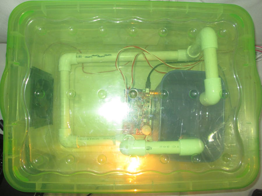
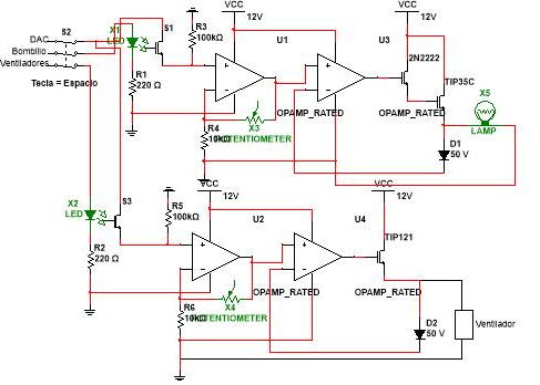
The idea is create a controlled environment to vermiculture, however the scope of this project is for any industrial process, i like to share this for all Hackster.io Users.
Construction of the structureHere i developed the code to generate the square signal and the PID controller for this plant (Code Attachment).
MATLAB Get DataMATLAB was used to get data through serial port, this data was saved on excel, this data later have been used to obtain the behavior of the plant in open loop.
With the data obtained in Excel with the MATLAB program through serial transmission, this data was analyzed with the Matlab tool "IDENT", in order to know the transfer function that models the plant.
after we have the data, we need create the vectors in this way
In these new variables will be stored the vectors to work, where "Cuadrada" is the input signal and "data" are the data obtained in the corresponding time of the signal, the values are entered as follows
After entering our data obtained through ident tool, we recognize the system worked, to do this you must select import data => Time domain data where the following menu will be displayed
In this menu should be configured the different variables that we are going to use for our case are cuadrada and data, it is also very important to take into account the sampling time of the signal obtained, for our case was 1 seconds. We obtain a new variable that for our case is called mydata
Observing that our new graph has a variation in 25.25 degrees plus or minus .25 degrees, which shows the behavior of the plant in open loop and the square signal generated by the data collection part. Now we must estimate different transfer functions by observing which one is closest to the behavior of the plant and which of these transfer functions we want to work.
In this menu we display the number of zeros and poles that we want our system to have, a comparison must be made between different transfer functions taking the function most similar to the behavior of the plant.
For development a transfer function was obtained that consisted of 1 Zero and 2 Polos, since it was the transfer function more similar to the behavior of the plant with a similarity of 72.08%.
Subsequently, we transfer our new transfer function to the MATLAB workspace where the discrete time processing is done with the transfer function.
We create the variables where we store our data to convert the format idtf to tf
After changing the format to tf, we can now pass in discrete time our transfer function by means of c2d as shown below
When discretizing we take the sampling frequency that we prefer, for the developed system is 20ms, now by means of the tool sisotool we obtain the value the following diagrams
We generate the controller for the system, in this way we obtain the following transfer function and perform the pseudocode
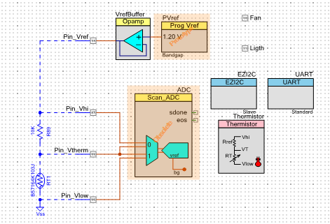
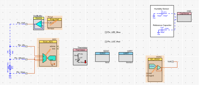
Now We have our pseudocodigo for PSoC program and now we can control the plant (CODE PID PSoC)
#include <project.h>
#include <stdio.h>

#define ADC_CHANNEL_VREF			(0u)
#define ADC_CHANNEL_VTH				(1u)
#define LED_ON						(0u)
#define LED_OFF						(1u)
#define TEMPERATURE_THRESHOLD_HIGH	(2700)
#define TEMPERATURE_THRESHOLD_LOW	(2500)
#define FILTER_COEFFICIENT_TEMPERATURE	(32u)
/* EzI2C Read/Write Boundary */
#define READ_WRITE_BOUNDARY         (0u)

/* Structure that holds the temperature sensor (thermistor) data                 */
/* Use __attribute__((packed)) for GCC and MDK compilers to pack structures      */
/* For other compilers use the corresponding directive.                          */
/* For example, for IAR use the following directive                              */
/* typedef __packed struct {..}struct_name;                                      */
typedef struct __attribute__((packed))
{
	int16 Vth;					/* Voltage across thermistor */
	uint16 Rth;					/* Thermistor resistance */
	int16 temperature;			/* Measured temperature */
}temperature_sensor_data;

/* Function Prototypes */
void InitResources(void);

/* Declare the i2cBuffer to exchange sensor data between Bridge Control
Panel (BCP) and PSoC Analog Coprocessor */
temperature_sensor_data i2cBuffer = {0, 0, 0};

/*******************************************************************************
* Function Name: main
********************************************************************************
*
* Summary:
*  This function initializes all the resources, and in an infinite loop, measures the temperature from the sensor
*  readings and to send the data over I2C.
*
* Parameters:
*  None
*
* Return:
*  int
*
* Side Effects:
*   None
*******************************************************************************/
int main()
{
    char stringBuffer[32u];
    /* Variables to hold the the ADC readings */
    int16 adcResultVREF, adcResultVTH;
    int n1=1;
    /* Filter input and output variables for Vref and Vth measurements */
    int16 filterOutputVref=0;
    int16 filterOutputVth=0;

    /* Variables to hold calculated resistance and temperature */
    int16 thermistorResistance, temperature;

    /* Variable to store the status returned by CyEnterCriticalSection()*/
    uint8 interruptState = 0;

    /* Enable global interrupts */
    CyGlobalIntEnable;

    /* Initialize hardware resources */
    InitResources();

    /* Infinite Loop */
    for(;;)
    {
        /* Check if the ADC data is ready */
        if(ADC_IsEndConversion(ADC_RETURN_STATUS))
        {
            /* Read the ADC result for reference and thermistor voltages */
            adcResultVREF = ADC_GetResult16(ADC_CHANNEL_VREF);
            adcResultVTH = ADC_GetResult16(ADC_CHANNEL_VTH);

            /* Low pass filter the measured ADC counts of Vref */
            filterOutputVref = (adcResultVREF + (FILTER_COEFFICIENT_TEMPERATURE - 1) * filterOutputVref) / FILTER_COEFFICIENT_TEMPERATURE;

            /* Low pass filter the measured ADC counts of Vth */
            filterOutputVth = (adcResultVTH + (FILTER_COEFFICIENT_TEMPERATURE - 1) * filterOutputVth) / FILTER_COEFFICIENT_TEMPERATURE;

            /* Calculate thermistor resistance */
            thermistorResistance = Thermistor_GetResistance(filterOutputVref, filterOutputVth);

            /* Calculate temperature in degree Celsius using the Component API */
            temperature = Thermistor_GetTemperature(thermistorResistance);

            /* Turn ON Ligth and turn OFF fan */

            while (n1==1){
             Fan_Write(0);
             Ligth_Write(1);
        uint16_t Temp1 = temperature;
        sprintf(stringBuffer, "%d",Temp1);
        UART_UartPutString(stringBuffer);
        CyDelay(20);
        adcResultVREF = ADC_GetResult16(ADC_CHANNEL_VREF);
            adcResultVTH = ADC_GetResult16(ADC_CHANNEL_VTH);

            /* Low pass filter the measured ADC counts of Vref */
            filterOutputVref = (adcResultVREF + (FILTER_COEFFICIENT_TEMPERATURE - 1) * filterOutputVref) / FILTER_COEFFICIENT_TEMPERATURE;

            /* Low pass filter the measured ADC counts of Vth */
            filterOutputVth = (adcResultVTH + (FILTER_COEFFICIENT_TEMPERATURE - 1) * filterOutputVth) / FILTER_COEFFICIENT_TEMPERATURE;

            /* Calculate thermistor resistance */
            thermistorResistance = Thermistor_GetResistance(filterOutputVref, filterOutputVth);

            /* Calculate temperature in degree Celsius using the Component API */
            temperature = Thermistor_GetTemperature(thermistorResistance);

             if(temperature>2549){
             n1=2;
            }
            }
            while (n1==2){
             Fan_Write(1);
             Ligth_Write(0);
        uint16_t Temp1 = temperature;
        sprintf(stringBuffer, "%d",Temp1);
        UART_UartPutString(stringBuffer);
        CyDelay(20);
        adcResultVREF = ADC_GetResult16(ADC_CHANNEL_VREF);
            adcResultVTH = ADC_GetResult16(ADC_CHANNEL_VTH);

            /* Low pass filter the measured ADC counts of Vref */
            filterOutputVref = (adcResultVREF + (FILTER_COEFFICIENT_TEMPERATURE - 1) * filterOutputVref) / FILTER_COEFFICIENT_TEMPERATURE;

            /* Low pass filter the measured ADC counts of Vth */
            filterOutputVth = (adcResultVTH + (FILTER_COEFFICIENT_TEMPERATURE - 1) * filterOutputVth) / FILTER_COEFFICIENT_TEMPERATURE;

            /* Calculate thermistor resistance */
            thermistorResistance = Thermistor_GetResistance(filterOutputVref, filterOutputVth);

            /* Calculate temperature in degree Celsius using the Component API */
            temperature = Thermistor_GetTemperature(thermistorResistance);

             if(temperature<2501){
             n1=1;
            }
            }
            /* Turn ON Ligth and turn OFF fan*/


			/* Enter critical section to check if I2C bus is busy or not */
            interruptState = CyEnterCriticalSection();

        	if(!(EZI2C_EzI2CGetActivity() & EZI2C_EZI2C_STATUS_BUSY))
        	{
                /* Update I2C Buffer */
                i2cBuffer.Rth = thermistorResistance;
                i2cBuffer.temperature = temperature;
                i2cBuffer.Vth = filterOutputVth;
            }

			/* Exit critical section */
            CyExitCriticalSection(interruptState);
        }
    }
}

/*******************************************************************************
* Function Name: void InitResources(void)
********************************************************************************
*
* Summary:
*  This function initializes all the hardware resources
*
* Parameters:
*  None
*
* Return:
*  None
*
* Side Effects:
*   None
*******************************************************************************/
void InitResources(void)
{
    /* Start EZI2C Slave Component and initialize buffer */
    EZI2C_Start();
    EZI2C_EzI2CSetBuffer1(sizeof(i2cBuffer), READ_WRITE_BOUNDARY, (uint8 *)&i2cBuffer);

    /* Start the Scanning SAR ADC Component and start conversion */
    ADC_Start();
    ADC_StartConvert();
    UART_Start();
    /* Start Reference buffer */
    VrefBuffer_Start();

    /* Start Programmable Voltage Reference */
    PVref_Start();

    /* Enable Programmable Voltage Reference */
    PVref_Enable();
}

/* [] END OF FILE */
serial_PSoC=serial('COM4','BaudRate',9600,'Parity','none','DataBits',8,'StopBits',1); %declaración de los parámetros de puerto serial
set(serial_PSoC,'InputBufferSize',4); %número de datos que se van a recibir en este caso yo estoy recibiendo por ejemplo 12.65
fopen(serial_PSoC);
contador=1; %inicializar un contador que se usa para llenar las posiciones de un vector donde se almacena cada dato recibido por el puerto serial
figure('Name','Conrolador ON/OFF Para generar la señal cuadrada de reconocimiento')        %Iniciar la ventana donde estará la gráfica
title('Grafica Valor del sensor de temperatura');             %Título que se le da a la gráfica
xlabel('Muestras en Segundos');                                    %Nombre del Eje x
ylabel('Temperatura (0.01°C)');                                 %Nombre del Eje y
hold on                                                %Retener la gráfica para que no se abra una nueva con cada dato
Numero_Muestras=2000;

while contador<=Numero_Muestras                        %Ciclo while para rellenar el vector ADC con los valores recibidos por el puerto serial
    recepcion=fscanf(serial_PSoC,'%f')'              %Asi se recibe un valor float por el puerto serial, es un vector columna.
    ADC(contador)=recepcion(1);                        %Asignacion de el vector recepción en la posicion 1 en el vector ADC en la posición en que se encuentre el contador
    plot(ADC)                                          %grafica los valores del vector ADC
    grid on                                            %Para poner la malla en la gráfica
    ylim([0 4000]);                                     %límites inferior y superior de la grafica en el eje y
    xlim([0 Numero_Muestras]);                         %límites inferior y superior de la grafica en el eje x
    drawnow                                            %Para actualizar los parámetros de la gráfica cada vez que pasa por el loop, ya que si no se pone
                                                       %unicamente con la función plot la imprimir{ia hasta que el loop se acabe
    contador=contador+1;                               %se modifica el contador para rellenar la siguiente posicion del vector ADC

    if contador>Numero_Muestras                       %condición para reiniciar el contador cuando se llega al número de muestras total
        hold off                                       %para "despegarse" de la gráfica un momento mientras el contador toma su valor inicial
                                                       %y asi cuando el loop vuelva a iniciarse se dara un efecto de osciloscopio                                                      %loop vuelva a
fclose(serial_PSoC);                                    %asi se cierra el puerto
delete(serial_PSoC);                                   %así se borra el puerto de la memoria de matlab
    end
end
/* Header File Includes */
#include <project.h>
#include <stdio.h>
#define ADC_CHANNEL_VREF			(0u)
#define ADC_CHANNEL_VTH				(1u)
#define LED_ON						(0u)
#define LED_OFF						(1u)
#define TEMPERATURE_THRESHOLD_HIGH	(3000)
#define TEMPERATURE_THRESHOLD_LOW	(2500)
/* IIR Filter coefficients for each signal */
/* Cut off frequency = fs/(2 * pi * iir_filter_constant).  In this project fs ~= 1 ksps.
This results in a cut-off frequency of 4.97 Hz.  We are using IIR filter as FIR requires
more order of filter to get the same cut-off frequency*/
#define FILTER_COEFFICIENT_TEMPERATURE	(32u)
/* EzI2C Read/Write Boundary */
#define READ_WRITE_BOUNDARY         (0u)
#define CAPACITANCE_AT_55_RH        (1800)
/* Sensitivity numerator and denominator indicate sensitivity of the sensor */
#define SENSITIVITY_NUMERATOR       (31)
#define SENSITIVITY_DENOMINATOR     (100)
/* Value of reference capacitor.  Note that this value includes the pin capacitance
    and the physical 180pF reference capacitor */
#define CREF                        (1930)
/* Offset Capacitance */
#define COFFSET                     (150)
/* This is raw count equivalent to trace capacitance */
#define OFFSETCOUNT                 (1536)
#define BUFFERSIZE                  (8)
/* Nominal humidity 55% */
#define NOMINAL_HUMIDITY            (550)
#define HUMIDITY_0_PERCENT          (0)
#define HUMIDITY_100_PERCENT        (1000)
#define HUMIDITY_50                 (500)

/* Structure that holds the temperature sensor (thermistor) data                 */
/* Use __attribute__((packed)) for GCC and MDK compilers to pack structures      */
/* For other compilers use the corresponding directive.                          */
/* For example, for IAR use the following directive                              */
/* typedef __packed struct {..}struct_name;                                      */
typedef struct __attribute__((packed))
{
	int16 Vth;					/* Voltage across thermistor */
	uint16 Rth;					/* Thermistor resistance */
	int16 temperature;			/* Measured temperature */
    uint16 humidityRawCounts;	/* Raw count from CapSense Component for the humidity sensor */
	uint16 capacitance;			/* Capacitance of the humidity sensor */
	uint16 humidity;			/* Measured humidity */
	uint16 rawCountsRefCap;     /* Raw count from CapSense Component for the Reference capacitor */
}temperature_sensor_data;

/* Function Prototypes */
void InitResources(void);
__inline uint16 CalculateCapacitance(uint16 rawCounts, uint16 refSensorCounts);
__inline uint16 CalculateHumidity(uint16 capacitance);
/* Declare the i2cBuffer to exchange sensor data between Bridge Control
Panel (BCP) and PSoC Analog Coprocessor */
temperature_sensor_data i2cBuffer = {0, 0, 0, 0, 0, 0, 0};

/*******************************************************************************
* Function Name: main
********************************************************************************
*
* Summary:
*  This function initializes all the resources, and in an infinite loop, measures the temperature from the sensor
*  readings and to send the data over I2C.
*
* Parameters:
*  None
*
* Return:
*  int
*
* Side Effects:
*   None
*******************************************************************************/
int main()
{
    char stringBuffer[32u];
    /* Variables to hold the the ADC readings */
    int16 adcResultVREF, adcResultVTH;
    char setpoint;
    char m1=0,m2=0,m3=0,m4=0,m5=0,m6=0;
    char error;

    /* Filter input and output variables for Vref and Vth measurements */
    int16 filterOutputVref=0;
    int16 filterOutputVth=0;

    /* Variables to hold calculated resistance and temperature */
    int16 thermistorResistance, temperature;

    /* Variable to store the status returned by CyEnterCriticalSection()*/
    uint8 interruptState = 0;
    /* Variable to hold calculated PWM duty cycle */
    uint16 pwmDutyCycle;

    /* Enable global interrupts */
    CyGlobalIntEnable;

    /* Initialize hardware resources */
    InitResources();

    /* Infinite Loop */
    for(;;)
    {
        /* Check if the ADC data is ready */
        if(ADC_IsEndConversion(ADC_RETURN_STATUS))
        {
            /* Read the ADC result for reference and thermistor voltages */
            adcResultVREF = ADC_GetResult16(ADC_CHANNEL_VREF);
            adcResultVTH = ADC_GetResult16(ADC_CHANNEL_VTH);

            /* Low pass filter the measured ADC counts of Vref */
            filterOutputVref = (adcResultVREF + (FILTER_COEFFICIENT_TEMPERATURE - 1) * filterOutputVref) / FILTER_COEFFICIENT_TEMPERATURE;

            /* Low pass filter the measured ADC counts of Vth */
            filterOutputVth = (adcResultVTH + (FILTER_COEFFICIENT_TEMPERATURE - 1) * filterOutputVth) / FILTER_COEFFICIENT_TEMPERATURE;

            /* Calculate thermistor resistance */
            thermistorResistance = Thermistor_GetResistance(filterOutputVref, filterOutputVth);

            /* Calculate temperature in degree Celsius using the Component API */
            temperature = Thermistor_GetTemperature(thermistorResistance);

            /* Turn ON Blue LED if Temperature is <= 25°C */
            if (temperature <= TEMPERATURE_THRESHOLD_LOW)
            {
                Pin_LED_Blue_Write(LED_ON);
                Pin_LED_Red_Write(LED_OFF);
            }
            /* Turn ON both Blue and Red LEDs if the temperature is >25°C and <=30°C */
            else if ((temperature > TEMPERATURE_THRESHOLD_LOW) && (temperature < TEMPERATURE_THRESHOLD_HIGH))
            {
                Pin_LED_Blue_Write(LED_ON);
                Pin_LED_Red_Write(LED_ON);
            }
            /* Turn ON Red LED if temperature is >30°C */
            else
            {
                Pin_LED_Blue_Write(LED_OFF);
                Pin_LED_Red_Write(LED_ON);
            }


			/* Enter critical section to check if I2C bus is busy or not */
            interruptState = CyEnterCriticalSection();

        	if(!(EZI2C_EzI2CGetActivity() & EZI2C_EZI2C_STATUS_BUSY))
        	{
                /* Update I2C Buffer */
                i2cBuffer.Rth = thermistorResistance;
                i2cBuffer.temperature = temperature;
                i2cBuffer.Vth = filterOutputVth;
                i2cBuffer.humidityRawCounts = CSD_BUTTON0_SNS0_RAW0_VALUE;
                i2cBuffer.rawCountsRefCap = CSD_BUTTON0_SNS1_RAW0_VALUE;
                /* Convert raw counts to capacitance */
                i2cBuffer.capacitance = CalculateCapacitance(i2cBuffer.humidityRawCounts, i2cBuffer.rawCountsRefCap);
                /* Calculate humidity */
                i2cBuffer.humidity = CalculateHumidity(i2cBuffer.capacitance);

            }

			/* Exit critical section */
            CyExitCriticalSection(interruptState);
        }

        /* Update the PWM duty cycle */

        uint16_t Temp1 = temperature;
        sprintf(stringBuffer, "%d",Temp1);
        UART_UartPutString(stringBuffer);
        sprintf(stringBuffer, "%d",CalculateHumidity(i2cBuffer.capacitance));
        UART_UartPutString(stringBuffer);
        setpoint=UART_UartGetChar();
        //Controlador Pseudocodigo
        error=setpoint-temperature;
        m3=error;
        m1=m2+4.3381*m3-4.3381*(0.9983)*m4;
        m5=m4;
        m4=m3;
        m2=m1;
        VDAC_SetValue(m1);

        //Delay para generar el tiempo de muestreo
        CyDelay(20);
    }
}

/*******************************************************************************
* Function Name: void InitResources(void)
********************************************************************************
*
* Summary:
*  This function initializes all the hardware resources
*
* Parameters:
*  None
*
* Return:
*  None
*
* Side Effects:
*   None
*******************************************************************************/
void InitResources(void)
{
    /* Start EZI2C Slave Component and initialize buffer */
    EZI2C_Start();
    EZI2C_EzI2CSetBuffer1(sizeof(i2cBuffer), READ_WRITE_BOUNDARY, (uint8 *)&i2cBuffer);

    /* Start the Scanning SAR ADC Component and start conversion */
    ADC_Start();
    ADC_StartConvert();
    UART_Start();
    VDAC_Start();
    /* Start Reference buffer */
    VrefBuffer_Start();

    /* Start Programmable Voltage Reference */
    PVref_Start();

    /* Enable Programmable Voltage Reference */
    PVref_Enable();
        /* Start CapSense Component */
    CSD_Start();

    //Start PWM
}

__inline uint16 CalculateCapacitance(uint16 rawCounts, uint16 refsensorCounts)
{
    return (uint16)((float)(rawCounts - OFFSETCOUNT) * (CREF - COFFSET) / (float)(refsensorCounts - OFFSETCOUNT));
}
__inline uint16 CalculateHumidity(uint16 capacitance)
{
    int16 humidity;
    int16 delta;

    /* Find capacitance difference from nominal capacitance at 55% RH */
    delta = capacitance - CAPACITANCE_AT_55_RH;

    /* Calculate humidity from capacitance difference and sensor sensitivity */
    humidity = ((delta * SENSITIVITY_DENOMINATOR) / SENSITIVITY_NUMERATOR) + NOMINAL_HUMIDITY;

    /* If humidity is less than zero, limit it to 0; If humidity is greater than 1000 (100%), limit to 1000 */
    humidity = (humidity < HUMIDITY_0_PERCENT) ? HUMIDITY_0_PERCENT : (humidity > HUMIDITY_100_PERCENT) ? HUMIDITY_100_PERCENT : humidity;

    /* Return Humidity value */
    return humidity;
}

/* [] END OF FILE */


Comments
Please log in or sign up to comment.