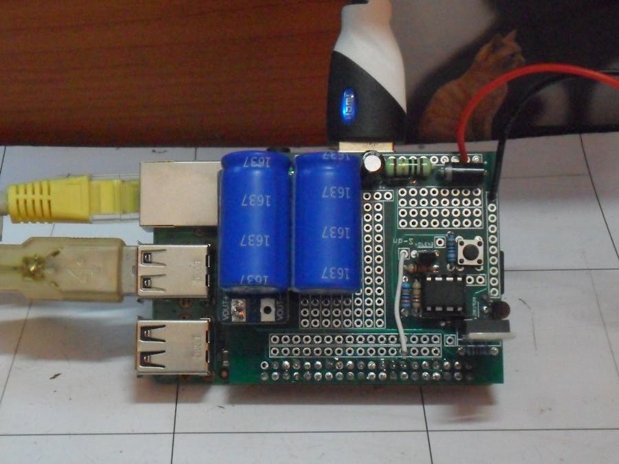
Whether it's a media center, file server, web server, robot, car PC, or an arcade console, a battery-less UPS for the Raspberry Pi gives it enough juice to shutdown properly and then boot back up when sufficient power is restored.
I've had one to many times have the power "fail" on my Pis. Many times it is a human "fail" by inadvertently pulling the plug.
Now I don't need to worry about that anymore.
The idea behind the safe shutdown and restart UPS is based on the function of a shutdown pin on the Pi.
Before going further, a shutdown script on the Pi must work by pulling a GPIO PIN to LOW. Once that is complete, the hardware can then be looked at. I have not (yet) mentioned how this is done as there are plenty of online tutorials out there.
Skills NeededSoldering expertise and knowledge of the electronic components listed below.
Programming, “Python” and “Bash” for the Pi, “C” for the ATtiny (and also knowing how to program one).
Components- Supercapacitors 40F* x 2
- 220uF capacitor
- Boost up converter
- ATtiny
- IC base 8-pin
- Perf board or PCB
- Headers
- Schottky diodes 2A x2
- Regular diode 1N4007 x2
- P-Ch MOSFET IRF5210 IRF4905 (or equivalent)
- NPN transistors 2N2222 or 2N3904 (or equivalent)
- Buttons (optional)
- Resistors 1/4 W 1Kx2, 3Kx2, 10Kx2, 47Kx2, 220Kx1
- Resistor 1W 10 or 20 Ohm
*40Fis dependent on load, 35F also worked fine on a raspberry Pi3.
FunctionWhen main +5V is connected, the capacitors begin charging.
When charge> 3V, the boost converter supplies 5V to the source and gate of the MOSFET and the ATtiny
The ATtiny boots up and monitors the capacitor voltage.
When capacitor voltage >3.9V, the ATtiny powers the PWR transistor grounding the MOSFET's gate and 5V is supplied to the Pi.
If the mains 5V drops and capacitor voltage < 3.8V and MOSFET still on, then the ATtiny powers the shutdown transistor whose collector is connected to the shutdown pin on the Pi, hence pulling it to LOW. A shutdown is triggered on the Pi, approximately 25 seconds later the ATtiny de-powers the PWR transistor, turning off the MOSFET and power is removed from the Pi.
ATtiny waits until mains 5V returns and capacitor voltage >3.9V to power the MOSFET transistor again and restore power to the Pi.
ATtiny LogicGather components first and test their function. Check for correct resistances and correct function of transistors and MOSFET.
Solder resistors first.
Diodes and 220 uF capacitor next.
Regulator is mounted on 3 male header pins. Solder the base of the pins to the PCB and trim the top after soldering onto the regulator.
Solder the IC base and the button in place.
Solder the capacitors and the header pins. Solder some (red) wire to the positive rail and(black wire) to the negative rail.
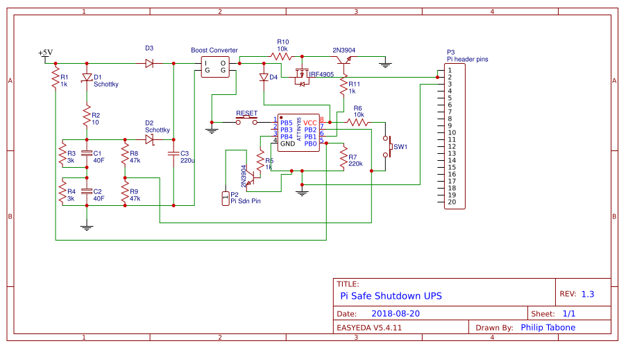
TestingApply power to the device, adjust the regulator to output (counter clockwise is increase) 5.1V at the VOUT point. Check the VCC at the IC base (see schematic) which should read approx 4.8V (due Vf of the diode). Check that there is 5.1V at the source and gate of the MOSFET.
On the IC base bridge VCC and PB1, and check that there is voltage at the base of the transistor controlling the MOSFET.
Bridge VCC and PB4 and check that there is voltage at the base of the transistor controlling the shutdown Pin.
Check voltage at PB2, this should read about ½ of the capacitor voltage (depending on their charge level).
Solder MOSFET and transistors. Connect a bit of wire from the collector pin of the shutdown transistor to the chosen shutdown pin on the Pi (above case BCM pin18).
On the IC base bridge VCC and PB1 and check that there is 5.1V at the Pi supply pins.
Bridge VCC and PB4 and check that the shutdown pin is pulled to ground.
LimitationsInput voltage (mains supply) max of 5.4V.
The button is a “force boot." It bypasses the capacitor reading and sends a higher voltage to the PB2. Using it will allow the Pi to boot; however, you will lose shutdown protection as the capacitors would not have reached their minimum level.
Further DevelopmentSome prototyping area on the PCB allows for further components.
PB3 is an open PIN on the ATtiny. It can be used for further logic if needed.
You can tweak the voltage at the MOSFET once setup by adjusting the boost converter. See Pi's input voltage limitations.
You can set a GPIO pin go high when the PI completes the shutdown. It is done by editing the /boot/config.txt and adding: dtoverlay=gpio-poweroff,gpiopin=17 At the end of the file (Replace "17" with the BCM pin you would like to use). Use that to trigger any other event on the remaining Attiny pin (for example).
I've been using these for a few months now. Please feel free to improve on the design and do comment on how you have done so.
Be careful with supercapacitors, when fully charged they can pack quite a punch, e.g. short circuit.


Comments
Please log in or sign up to comment.