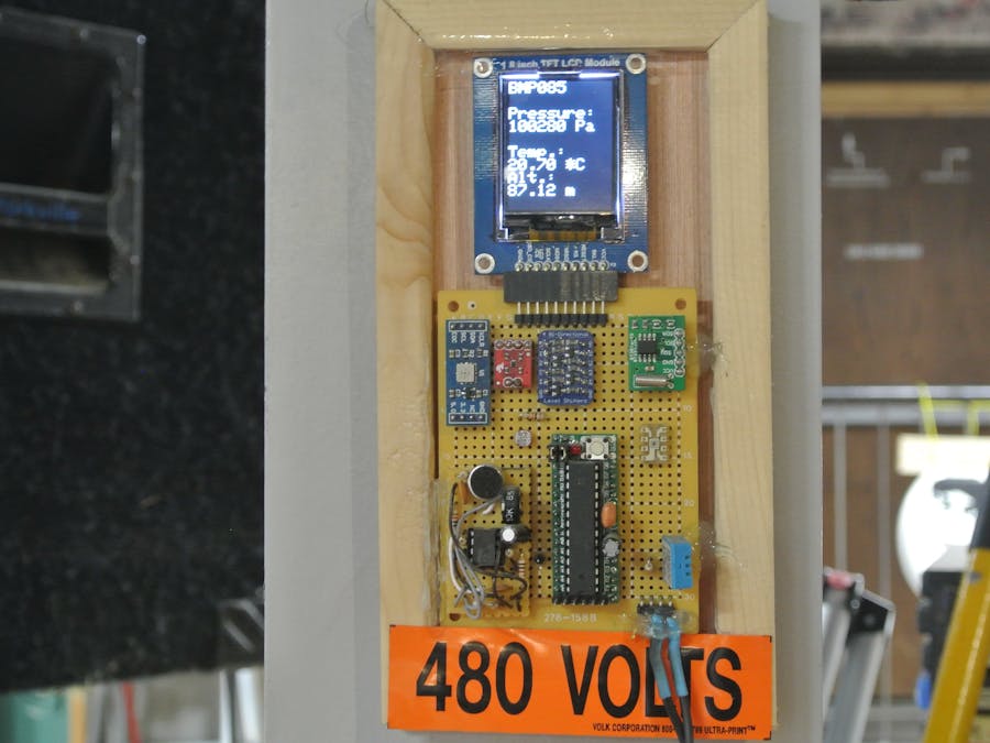
In the medieval times of the LVL1 Hackerspace, The Director of Legal Evil (Emeritus) decided to create a sensor array. The board was built with the ancient art of wirewrap. Original write up on the hackerspace wiki (http://wiki.lvl1.org/Father_AI_Sensor_Array). This board was then prepared for service when suddenly the hackerspace moved.
The sensor array was then overhauled from its clandestine layout and function into a hackerspace sensor display wall hanger. A TFT LCD display was added and a Level Shifting board was added to replace the discrete FET and resistor pairs.
Both versions used lines D0, D1 for debugging and diagnostics.
But the display was hanging on the wall in the hackerspace, so how could it help me monitor the space remotely? The answer came in the form of the Blynk. This device came to my attention via a contest on "Hackster.io". This board would allow me to send data to my google nexus 7 tablet. All I had to do was figure out how.
I began with the Blynk tutorials. Several ideas formed and I prepared myself for some invasive programming of the Sensor Array and the Blynk. But then I saw the tutorial example of the "Terminal" widget and all came into focus. All I had to do was clean up the serial data stream coming from the sensor array and feed it through to the Blynk. The only additional wiring would be to level shift the serial 5v from the Arduino to 3.3v for the Blynk.
Now, the onboard level shifter was tied up in the existing device and prying through the hot glue affixing the board to the frame was not appealing. I would need to wire a second level shifter board between the Blynk and the sensor array.
The existing sensor array has an FTDI programming connector for the Arduino clone. The FTDI connector will be used to provide power and serial lines for the Blynk. As mentioned before, a level shifter is needed between the board's serial lines.
Remember, the TXD clip goes to the RXD on the Blynk and the RXD clip goes to the TXD on the Blynk.
Actual wiring swaps the yellow and green leads, but the board is as designed. Although this project consists of a simple level shifter and wiring harness, isn't making the IOT easy the whole point of the Blynk. The sensor array was already IOT ready even though I didn't realize it at first. The Blynk just happened to ship with everything I needed.
Additional program is needed to clean up the messages being sent but that is as easy as using the Blynk.
A few details:
I used the schematics for the Blynk board on the SparkFun site to verify that the serial lines on the board were the same lines that the USB used on the Terminal Demo tutorial. The power supplied to the Blynk board is the power siphoned from the FDTI connector on the Arduino clone. The 3.3V regulator on the Blynk supplies the 3.3V for the level shifter. The 480 Volt sticker is for show.
I will be attending the Detroit Maker Faire 2016, where I will monitor the LVL1 Hackerspace via the Blynk. Stop by the LVL1 Hackspace tent and we'll talk about your Blynk project.
Director of Legal Evil (Emeritus) for LVL1 Hackerspace Louisville, Ky


Comments
Please log in or sign up to comment.