

Hardware components | ||||||
 |
| × | 1 | |||
| × | 1 | ||||
| × | 1 | ||||
 |
| × | 13 | |||
 |
| × | 2 | |||
| × | 13 | ||||
 |
| × | 1 | |||
 |
| × | 1 | |||
Software apps and online services | ||||||
 |
| |||||
Hand tools and fabrication machines | ||||||
 |
| |||||
I was digging in my box of random electronic things that I don't use anymore and hope to find a way to recycle, one day and found this cute little cellphone.
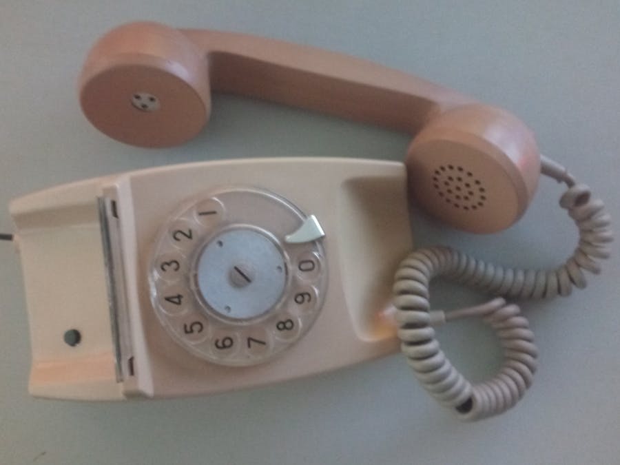
And I thought "What if I took the cute little phone, tore it apart, ripped its entrails out and attached it to another older less cute phone!" And so I went and bought an old rotary dial telephone and started my adventure...
FYI, old rotary dial phones aren't easy to come by these days.
Unfortunately, for this project, I can only show you a few pictures and share the code with you. I have no idea how much changes are going to be required in the code if you use another cellphone than the one I used.
But let's start on the easy piece. The dial itself.
When I started this project, this was my biggest worry. How was I going to read the dial? And the answer was... disappointingly easy.
The back of the dial is actually super simple. I'm guessing that the technology didn't vary that much from one phone to the other back then so you'll probably find a similar configuration when taking your old telephone apart...
The colors of the wires on the prototyping board below match the colors on the dial above. (The pink wire on my dial is connected to the brown. That's why there's no pink on the diagram)
In the code, this is what does the work:
 int activeState = PIND;
 activeState = PIND & PULSE_ACTIVE;
 while(activeState){
   off_hook = true;
   unsigned long val = myPulseIn(3, LOW, PULSE_IN_TIMEOUT);
   //Serial.println(val); //for debugging
   if(val > MIN_VALID_PULSE && val < MAX_VALID_PULSE){
     digit++;
   }
   activeState = PIND;
   activeState = PIND & PULSE_ACTIVE;
   hasDigit = true;
 }
On my dial, when nothing is happening on the dial, the orange wire reads 0v because the switch is open on that side, the grey one is closed so it reads 3.3v (But we don't care). When the dial is wound, the orange wire gets connected. This causes activeState to be true (sort of). Then when the dial unwinds, the other switch will start pulsing and the myPulseIn function counts the amount of time between on and off states. Everytime the switch is off for between MIN_VALID_PULSE (50000) and MAX_VALID_PULSE (150000 units of time - those aren't human units), digit is incremented. For a 1 this happens only once, for a 3, three times,... you get the idea :D
The values are defined at the top of the code. As I realised with the help of JKF, my dial was really old and slow. His pulses are a lot faster and didn't fit in the 50000 - 150000 bracket. By using some of the Serial debug lines provided, you'll be able to get values and find a bracket that works for you.
#define MIN_VALID_PULSE 50000
#define MAX_VALID_PULSE 150000
#define PULSE_IN_TIMEOUT 300000
Now we have a digit to dial, so we dial it. The dialCellDigit does this and it's explained in the code.
Step 3Next we connect this to the cellphone:
The keypad of my little phone works on the same principle as the keypad on the Arduino tutorial. The left side of the prototype board shows the circuit needed to connect one button. On my cellphone, the green wire is connected to a point on the keyboard that corresponds to a row and the blue one to a column. This is easy to figure out once the phone is open by connecting a wire between various points on the naked keypad and checking what it does.
The little black ICs are Opto-Isolators. They work more or less like relays so the Arduino circuit stays independent from the phone one.
Once you have figured out your rows and columns, you just have to connect them to one another correctly. 1,2,3 on the keypad will have the same row (green) but different columns (blue), 4 has the same column as 1 (blue) but a different row (green) .
Step 4The "Call" and "Hang Up" buttons were weird because they both had their own special green and blue.
Once you have the dial talking to the keypad, the rest becomes assembly. You'll need to take apart the receiver to figure out which wires are for the microphone and which are for the speaker. I couldn't figure out the positive and negative for each set on my receiver. It doesn't seem to really matter.
They just need to get connected to their counterpart on the cellphone. The speaker was easy because the poles on the circuit board were about 3mm x 3mm. The microphone on the other hand, is located at the bottom of the keypad somewhere. The connection poles are minuscule and less than a millimeter apart.
And at this point, I have to take a second to officially thank Chantal for her help with the soldering. She did 80% of the soldering onto the 2 circuit boards and she did the microphone one! Without her, I don't think my phone would have had a microphone at all.
On the chassis of the old telephone, we need to add wiring to connect the 'hang-up' lever button of the old telephone to our Arduino. I used pin 18 (A4) for this. My phone had 3 of those lever switches. I used the one that was normally closed so the current would only flow when the phone is off the hook (Which is less often than on hook)
In the casing of the telephone, I drilled a small hole to squeeze a push button that I then connected directly to the green-blue wire combination for the 'Dial' button on the cellphone.
Step 5Finally, we squeeze everything back into the casing of the old telephone
And we put the case back on.
I use a standard mini USB cable to connect the Arduino Nano (red circuit board above) to the power and run my phone from a portable cellphone charger. There's already a gap to let the wire out because this phone used to connect to a land line.
On a final note,
#define PHONE_NUMBER_LENGTH 10
This defines the number of digits the cellphone will dial before calling automatically. In SA, we have 10 digit numers. You might have to change this value for your country.
The push button that I added on the case is for international numbers. Here they start with 00 ('+' on your cellphone is the shortcut for this but good luck getting a '+' out of the rotary dialer :)
This is the code in charge of preventing automatic dialing at PHONE_NUMBER_LENGTH digits.
if(digit == 10 && digitCount == 2)
   digit2zero = true;
It only checks that the second digit is a 0 (that's because in SA, all numbers start with 0. You will have to modify this also to get the international calling working if your country works differently.
ConclusionsIf you need explanations on the code or additional details, please feel free to ask. I can't however help you with technical questions. I don't know cellphones, nor do I know old telephones. This is one specific cellphone connecting to one specific telephone and a lot of trial and error.
I hope you got this far and got excited about building one of those!
If you do, please drop me a message or leave a comment and we can make a plan for me to call you OldArduiPhone to OldArduiPhone!


_3u05Tpwasz.png?auto=compress%2Cformat&w=40&h=40&fit=fillmax&bg=fff&dpr=2)
Comments