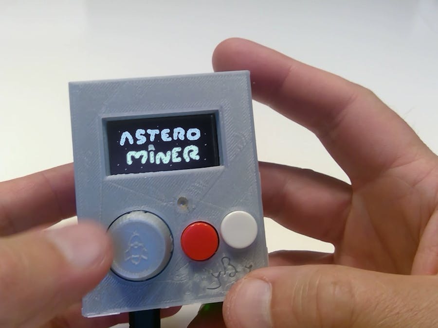
It's cool how small the Arduboys can be. Nevertheless I decided to design something with the original Uno/Leonardo form factor. They are not that big. My final product won't be bigger than a Gameboy. I also wanted to use the Uno/Leonardo form factor, because my design will never go to mass production. However it will be easily reproduced by anyone. No soldering on the Leonardo! It can any time be detached and used for other projects.
My two leading ideas for this project are:
- The four directional buttons of a standard Arduboy are replaced by a DIY analog joystick
- The Uno/Leonardo form factor together with a 1.3" OLED display
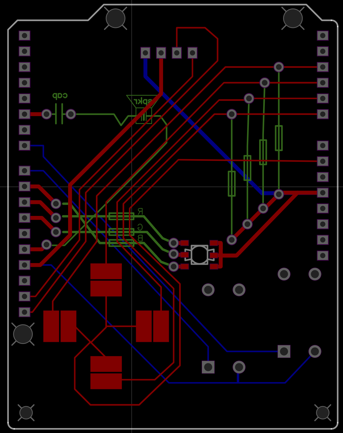
I designed and ordered the PCB from OSH. The board will have headers that attach to the Leonardo. The board will fit the 1.3" display, one SMD RGB LED and two push buttons. It will also have four pressure sensitive pads for the joystick. On the opposite side there is room for resistors needed for the joystick, resistors for the LED and some room for the piezo speaker and its resistor.
The board has the Arduino Uno/Leonardo form factor. Male pin headers are to be soldered to the edges so that this board can be attached to the Arduino Leonardo. The most special part in the design are the four pads (a) for the joystick. Each pad has two halves not connected with each other. One half goes to an analog input pin and further through a pullup resistor to 5V. The other half goes to GND. A piece of conductive plastic foam touches the pad and creates a connection with a resistance between the halves. The harder one presses, the lower the resistance.
The display connects to the four pins at the top (b). Yes, four pins means I2C. The traces go to the SCL and SDA pins of the Arduino (c). Only later I learned that pins 4 and 6 were the ones to be used with the I2C display. Instead of hacking the lib to comply with the SCL and SDA connection, I decided to cut the header pins at (c) and solder jumpers from the display pins to pins 4 and 6.
Below the display is an SMD RGB LED (d), the only surface mounted component. Tricky to solder, but easy to fit in. And way too bright for this purpose. The two buttons (e) are standard 12 mm push buttons.
The bottom side has the pullup resistors (f) for the joystick and resistors for the RGB LED (g). The silk print of the board shows a speaker (h) and suggests a capacitor to be connected in series. In my prototype I use a piezo speaker and a 150 Ohm resistor instead.
The joystickThe joystick is a 3D printed round button pressing on the four pads on the PCB.
The bottom side of the button has four holes (a) for the conductive foam pieces. A steel spring is attached to the middle (b).
The spring presses the button against the cover of the 3D printed case. The case has "cradles" for the four pegs of the button, which will hold the button in correct position and direction.
One would think two analog pins would be enough for a joystick like this. The opposite directions could together form a voltage divider using the same analog pin. But since the joystick is not a stick, but a large button, the button can still be pressed at the middle. The four analog ports will simply create more information about the button.
The demo gameI needed a new game, where the advantages of the analog joystick will be clear. The gameplay of Astero Miner is simple. Travel through the asteroid belt from rock to rock and land on them.
The demo version of the game includes the motion control, flame animation, a few sounds, landing and collision. Just enough to give a feel of how the analog joystick button works in games. The asteroids have no gravity, so you have to use thrusts in all four directions.
Further development of the game will include an idea of gameplay. Perfect landing requires slow approach from above with almost no sideway velocity. Collect energy, oxygen and gold from each asteroid. Avoid running out of oxygen and energy. Return to the base with the gold.
Yes, it's a side view game. What did you expect from 128*64, 1 bit colour? That said, I would be thrilled by the mare idea of having a cockpit view 3D game in this resolution!
Wrong componentsThis chapter is about getting an SH1106 display with I2C work with Arduboy. Read this only if you insist on using an SH1106/I2C display.
Not knowing everything about Arduboys, I ordered the wrong display and designed the PCB for that. But the great community came to rescue. The Arduboy is designed to work with a SSD1306 display with SPI protocol. What I ordered was a SH1106 display with I2C protocol. Apparently there are very few 1.3" displays on the market with SSD1306 and SPI. And the one I ordered had no specs at all! But I was in a hurry and I relied on getting it work. Well, it worked beautifully on my Arduino, when I just tested the ordinary U8g2 example programs for displays.
Then I learned about the Arduboy-homemade-package, which gave more options for the display. But still there was no option for SH1106 with I2C.
Then I learned that evgenykzz2 had added the SH1106/I2C option to the homemade-package. It can be found here:
https://github.com/evgenykzz2/Arduboy-homemade-package
Not familiar with GitHub, I just went through all the files he had changed 3 months ago. They were the ones where he had added the I2C for SH1106. I actually opened the files in my browser and copy-pasted the content into the corresponding files in my previous installation of the homemade-package. The proper way would be to install the whole package from evgenykzz2's Git. Anyway, the files I got from his site were:
- board-package-source/boards.txt
- board-package-source/libraries/Arduboy/src/core/core.cpp
- board-package-source/libraries/Arduboy/src/core/core.h
- board-package-source/libraries/Arduboy2/src/Arduboy2Core.cpp
- board-package-source/libraries/Arduboy2/src/Arduboy2Core.h
I might have a backwardish installation of the Arduino IDE, don't know. But these files are in the following folders on my computer:
C:\Users\johan\AppData\Local\Arduino15\packages\arduboy-homemade\hardware\avr\1.2.9\boards.txt

C:\Users\johan\AppData\Local\Arduino15\packages\arduboy-homemade\hardware\avr\1.2.9\libraries\Arduboy\src\core (core.cpp and core.h)

C:\Users\johan\AppData\Local\Arduino15\packages\arduboy-homemade\hardware\avr\1.2.9\libraries\Arduboy2\src (Arduboy2Core.cpp and Arduboy2Core.h)
Yet one more thing I had to do. For some reasons the I2C hack of evgenykzz2 doesn't use the standard SCL and SDA pins on the Arduino, but the digital pins 4 and 6. I had already designed a nice PCB, where the SCL and SDA pins of the display connected to the SCL and SDA pins on the Arduino. This worked with any other sample programs, but not with this Arduboy-homemade package. So I cut the two header pins that go to the SCL and SDA pins on the Arduino and soldered two jumper wires from the display to the pins 4 and 6 on the top of my PCB. Now my homemade Arduboy doesn't run other programs, only Arduboy programs.
Hacking the libAn Arduboy is supposed to have four directional buttons. They are connected to A0 - A3. But because an Arduboy has just buttons, the lib disables the analog-to-digital-converter to save power. To be able to read the pins A0 - A3 as analog inputs, one has to add power_adc_enable(); to the code, after begin();
That is not hacking the lib, yet. Next thing is!
Replacing the four buttons with a DIY analog four pin joystick needs still to take care of the buttonState(); member function. Depending on your joystick, the pins will return anything between 0 and 1023. The buttonState(); will treat 1023 as HIGH and 0 as low. You need to test your joystick and decide for each direction, what is the threshold for triggering the button. Say your joystick gives a value 1012 when in rest and 542 when pushing hard to the left. A threshold value of 600 could be fine to trigger the left button.
This is from Arduboy2Core.cpp:
uint8_t Arduboy2Core::buttonsState()
{
    uint8_t buttons;
#ifdef ARDUBOY_10
    // up, right, left, down
    buttons = ((~PINF) &
        (_BV(UP_BUTTON_BIT) | _BV(RIGHT_BUTTON_BIT) |
        _BV(LEFT_BUTTON_BIT) | _BV(DOWN_BUTTON_BIT)));
    // A
    if (bitRead(A_BUTTON_PORTIN, A_BUTTON_BIT) == 0) { buttons |= A_BUTTON; }
    // B
    if (bitRead(B_BUTTON_PORTIN, B_BUTTON_BIT) == 0) { buttons |= B_BUTTON; }
#elif defined(AB_DEVKIT)

    ...

    return buttons;
}
I'd change it to this:
#define LEFT_THRESHOLD     600
#define UP_THRESHOLD       600
#define RIGHT_THRESHOLD    600
#define DOWN_THRESHOLD     600

uint8_t Arduboy2Core::buttonsState()
{
    uint8_t buttons;
#ifdef JOYBOY
    // up, right, left, down
    int a0, b0, c0, d0;
    analogRead(A0);       // read each port twice and save the second
    a0 = analogRead(A0);  // reading to give time for the ADC to switch
    analogRead(A1);
    a1 = analogRead(A1);
    analogRead(A2);
    a2 = analogRead(A2);
    analogRead(A3);
    a3 = analogRead(A3);

    buttons = 0;
    bitWrite(buttons, LEFT_BUTTON_BIT, (a3 < LEFT_THRESHOLD));
    bitWrite(buttons, UP_BUTTON_BIT, (a2< UP_THRESHOLD));
    bitWrite(buttons, RIGHT_BUTTON_BIT, (a1 < RIGHT_THRESHOLD));
    bitWrite(buttons, DOWN_BUTTON_BIT, (a0 < DOWN_THRESHOLD));

    // A
    if (bitRead(A_BUTTON_PORTIN, A_BUTTON_BIT) == 0) { buttons |= A_BUTTON; }
    // B
    if (bitRead(B_BUTTON_PORTIN, B_BUTTON_BIT) == 0) { buttons |= B_BUTTON; }
#elif defined(ARDUBOY_10)
    // up, right, left, down
    buttons = ((~PINF) &
        (_BV(UP_BUTTON_BIT) | _BV(RIGHT_BUTTON_BIT) |
        _BV(LEFT_BUTTON_BIT) | _BV(DOWN_BUTTON_BIT)));

    ...

    return buttons;
}
The idea came from reading discussions in community.arduboy.com, where similar approaches have been taken to expand the input capabilities of the Arduboy. The original code has an ARDUBOY_10 section and an AB_DEVKIT section. They activate through #define compiler directive. I add a JOYBOY section and in the beginning of the Arduboy2Core.h file, I add #define JOYBOY. The purpose is to set the bits for up, down, left and right buttons according to the values read. For this, the threshold values are to be defined. I want to underline that I haven't tested this yet. This is on the todo list for further development.
Another approach to making the analog joystick work with an unchanged original Arduboy library is to adjust the voltage divider so that the conductive foam really manages to draw the voltage low enough for digitalRead() to read it as LOW. This could be achieved with trimpots working as variable resistors in the place of the 10k resistors.
Testing a standard Arduboy gameImprovements to doInstead of having the pieces of conductive plastic foam work as springs pushing against the pads on the PCB, I will have real steel stpings (model ballpoint pen) there. They will sit steady against the button. The central spring might not be needed. Instead of conductive foam I will use conductive plastic film (Velostat).
As mentioned earlier, SSD1306 with SPI is the display to be used, not SH1106 with I2C.
The joystick button needs more testing. Right now it doesn't tilt nicely, unless you press it a bit to release it from the edges along the hole in which it is placed. It's all 3D printed surfaces against each other.
The device needs a battery. Right now it's powered through the micro USB or the barrel connector.


Comments
Please log in or sign up to comment.