The SEEED Xiao series features a small footprint and many microcontrollers for various applications, all at low prices. This is one of the reasons why I use them in many of my projects. When I heard about the SEEED Fusion Keyboard design contest, it was clear to me that I wanted to participate. Since I've been playing around with LCD displays a lot lately, I wanted to use a display I had lying around. It was a 1.47 inch LCD display from Waveshare with a resolution of 172x320. I had never used this display in combination with the RP2040. So the first step was to hook up the display and get it working. The display came with a ST7789V3 driver. Fortunately, the TFT_ESPI library supported this driver. The only thing I had to do was to change the pinout definition and select the correct display driver. In short: Open the Arduino TFT_eSPI Library folder and navigate to the "User_Setups" folder. Then open Setup72_ESP32_ST7789_172x320.h change the Pinout to:
Even though the file says ESP32, it will also work with the RP2040. Save the file and navigate back to the TFT_eSPI folder. Then open User_Setup_Select. Then comment out the #include <User_Setup.h> line and add #include <User_Setups/Setup72_ESP32_ST7789_172x320.h>. Save the file (make sure that all the other User Setups are commented out). After that, the display worked for me.
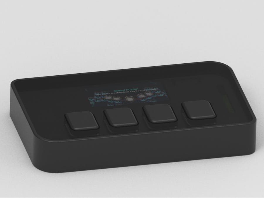
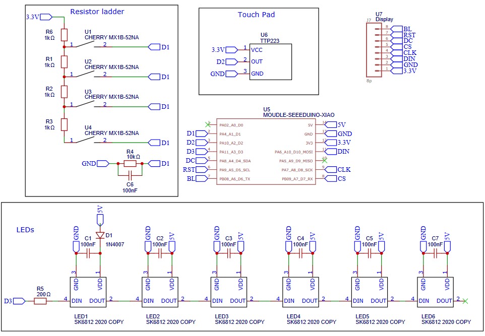
After verifying that the display works, I started to work on the Design. I designed the circuit in EasyEDA and the housing in Fusion360 + Solid Edge and Keyshot for rendering. The final Design looked like this:
While designing the PCB, I also worked parallel in Fusion 360 to design the housing and all the other components. For this purpose, I exported the outer shape of the PCB as a DXF file and imported it into Fusion360. I prefer this approach because I can easily adjust and update the DXF file in Fusion360 and then import it back into EasyEDA. After several iterations, the outer shape of the PCB looked like this:
Before I ordered the PCB, I wanted to make sure that all the dimensions were correct and all the components fit. So I just 3D printed the PCB and placed all the major components on it. I haven't seen many people do this, but in my opinion it's a good way to check the PCB design. Also, this dummy PCB can later be used to check the design of the case.
After I was happy with the PCB design, I purchased it on the Seed Fusion Website. The process was very easy and quick. I was happy when the PCB design was approved. Instead of just waiting for the PCB to arrive, I went on with designing the housing and all the inner parts in detail. While designing the parts, I like to use Keyshot, which enables me to create realistic looking renders. After I was happy, I 3d printed all the parts & used a Lasercutter to cut out the acrylic cover. The final structure looked like this:
I also worked on the code, while waiting for the PCB. Fortunately, I didn't have to wait very long. The PCB arrived after just one week. I was not expecting the PCB to arrive that fast! But that was great because I could optimize the code with the final PCB. The quality of the PCB was amazing and also the outer dimensions were better than I expected:
After receiving, I soldered all the components and tested if everything works properly. I started with the Neopixel LEDs continued with the mechanical switches and finally the Display. Everything worked as expected and I was very happy. Here are some pictures showing the PCB with all the components on it:
The PCB features an LCD Screen which displays four icons to clarify the function of the mechanical switches. Next to the PCB is a touch sensor. When the touch sensor is activated, the display will scroll to the next page and display different icons. Aditionally there are several Neopixel Led's which can be used to signalize that a mechanical switch has been pressed. I also added the SEEED Studio Intro and the Challenge banner, which are shown when the Shortcut Keyboard is powered on. Here are some videos showing all the functions:
CodeThe pages/symbols can be easily changed. Everything that needs to be changed is marked in the code. I used Figma to create the different pages. To do this, I simply created a frame with a resolution of 320x172 and inserted four icons. Here you can see the different pages I created. On the left side there are just some general functions (like copy, paste,...). On the right side I created shortcuts for Fusion 360.
In order to display these on the LCD Screen, I exported the individual pages as PNG's. These PNG's then needed to be converted to RGB565 files. The easiest way to do this, was to use a tool called ImageConverter565. The tool can be found in the UTFT library and can be downloaded here.
These files than need to be copied to the Arduino Project folder and need to be included in the code. Also, the color of the individual pages can be set and the individual Commands, that should be sent when the mechanical switches are pressed, need to be defined. The last step is to define the number of pages. All the other things are handled by the rest of the code. The full project folder can be found in the GitHub repository, which is linked below.
ConclusionI was happy with the outcome of this project. I hope it also shows that the Seeeduino Xiao is perfect for projects like this. Likewise, I was very pleased with the quality of the SEEED Fusion board & I would like to thank the SEEED team for organizing competitions like this one. Here are a few more pictures of the build:
One thing I would probably change is to remove the touch button and the Neopixel LEDs and use a larger LCD screen instead.Also, I would probably look for an LCD module that I could solder directly to the board. I would also replace the mechanical buttons with smaller push buttons. This way it would be possible to add additional buttons. It would also be possible to reduce the thickness of the case and board. Here is a rendering of what I have in mind:


_t9PF3orMPd.png?auto=compress%2Cformat&w=40&h=40&fit=fillmax&bg=fff&dpr=2)


Comments
Please log in or sign up to comment.