


Hardware components | ||||||
_ztBMuBhMHo.jpg?auto=compress%2Cformat&w=48&h=48&fit=fill&bg=ffffff) |
| × | 1 | |||
 |
| × | 30 | |||
| × | 1 | ||||
 |
| × | 6 | |||
 |
| × | 1 | |||
Hand tools and fabrication machines | ||||||
 |
| |||||
 |
| |||||
| ||||||
 |
| |||||
Warning: To complete this project more efforts than expected were needed. To solder all the LEDs and the wires at the right positions will take several hours of concentrated work.
If you are familiar with Charlieplexing you can skip the next paragraphs.
Introduction to CharlieplexingIn the field of logic, scientists and technicians have been working with true and false for more than 2000 years.
As from 1970 microprocessors were to communicate with a multitude of components using bus systems so it became necessary to disable outputs of deselected modules by introducing a third state with high impedance (High-Z). These outputs are called tri-state.
Some years later, with the introduction of microcontrollers, it became possible to set even single lines to High-Z rather than a complete bus. In 1995, Charlie Allen, engineer at Maxim Integrated, used this feature to extend the well-known multiplexing technique to drive more components with less output lines. Since then, it is called Chalieplexing.
For instance, to drive 56 LEDs with standard multiplexing you need 7+8=15 lines. With Charlieplexing you only need 8 lines.
So, how does Charlieplexing work?
Think about a group of children throwing balls. Each of the children is able to throw and to catch. At each moment, only one child is allowed to throw and only one is allowed to catch. So, how many ways the balls can take? Keep in mind you cannot throw a ball to yourself. Of course, each of the children has access to an infinite resource of balls, and there would be some kind of collection of caught balls.
Unfortunately, there is a drawback with Charlieplexing: if there is a failure with one or more of the LEDs, may it be missing, short-cut or leading in both directions, it is nearly impossible to locate the failure exactly. So do it very carefully.
And there is another drawback: all the LEDs should have approximately the same forward voltage. So you can mix red, yellow and green LEDs, but not white or blue ones.
In order to separate the function of the main program from driving the LEDs, the latter was relocated to an interrupt service routine handled by one of the timers. As in the Arduino system Timer0-Overflow (ISR) is working all of the time an additional ISR on the COMPA event of Timer0 was added to handle the LEDs. By misusing Timer0 all the other Timers are still available for the main program.
Part OneFor experts only: ISRs should be as short as possible. The TIMER0_COMPA_vect is called once each millisecond (exactly the same as TIMER0_OVF_vect), and it takes just 10 microseconds to execute.
So the main program just has to set values in a kind of video RAM where the ISR finds and treats it as intended.
So, how many lines are available to drive the LEDs? If you are going to handle them by using the pinMode and digitalWrite commands you can use as many pins as are available, but the routine would get quite slow. So you better go for pins which belong to the same port, may it be PORTB, PORTC, or PORTD. In case of PORTD, do not use the serial pins RX and TX. Doing it this way you can simply use the PORT and DDR registers to enable the LEDs.
Only the letter (B, C, or D) describing the port you are going to use has to be entered in the first #define statement of the code. By means of some tricky macros the selected port can be used in different statements.
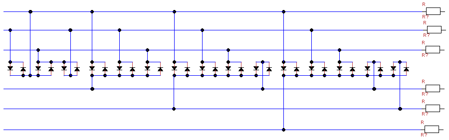
This is the schematic of Charlieplexing. The resistors have to be connected to Arduino pins.
Using a strip board you have most of the connections ready. Actually a bit too much. At certain positions you have to interrupt the strips. This can be done by carefully drilling at those positions with a 3 mm drill.
The LEDs of each pair have to be inserted antiparallel. In case you mixed the orientation of one pair you can correct this in the software. The blue wires you can get when you shorten the legs of the LEDs.
Instead of arranging the LEDs in a row you can put the six terminals at the corners of a regular hexagon. We used a CD cover to fix the screws. You can see the six sides of the hexagon and all the diagonals. Between each pair of terminals there is an LED. In this example we used 15 DUO LEDs which light up red or green depending on the polarity.
When you start the program it might look like this:
Sometimes you need more power to drive the LEDs. This can be done using a "tri-state-amplifier", originally seen at Digikey:
And this is the schematics for six of them:
you can build the amplifiers on a breadboard and connect them to an Arduino UNO like this:
Here you get a close-up to the breadboard:
Now you can arrange that 30 LEDs in a row and use a sine function to activate them:
For another project, I needed some Duo-LEDs as shown in fig 5 and 6. But in this case, I wanted to simplify the wiring; the cost is needing some more pins. Actually, I wanted to drive seven Duo-LEDs, what normally takes fourteen pins. But doing it this way I needed only seven pins:
The power of Charlieplexing enables you to drive 7 * 6 = 42 LEDs using 7 pins, but the wiring is getting more and more complex.
The wiring used here is very easy, and so is the software:
void setup() {}

int i = 1;

void loop() {
  for (int h = 0; h < 5; h++) {
    for (int j = 1, k = 2; j <= 7; j++, k++) {
      if (k == 8) k = 1;
      pinMode(k, OUTPUT);
      boolean b = j == i;
      digitalWrite(j, b);
      digitalWrite(k, !b);
      delay(3);
      pinMode(j, INPUT);
    }
  }
  i++;
  if (i > 7) i = 1;
}
That is all you need. At the end of the day, I decided to remove the resistors as each LED is only on for 3 milli-seconds and then off for 18 milli-seconds. Do not do this when you use an Arduino UNO R4 processor.
The code inside the loop function could be moved to an ISR routine as shown above.


Comments
Please log in or sign up to comment.