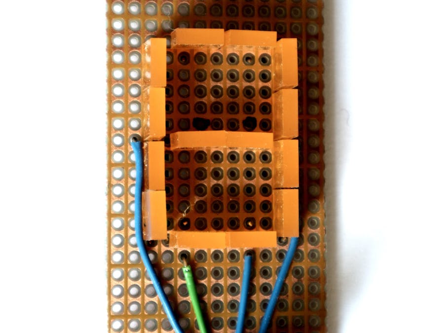
Usually, when you need some numerical output, it takes you at least seven pins of your microcontroller (except you use a display with an internal controller or a decoder/driver like SN7447/48). That is because they have common anodes or cathodes. But when you use single LEDs to form a digit you have separate anodes or cathodes and can connect them in your own style. The method made famous by Charlie Allen enables you to switch a huge number of diodes with a fraction of pins. With only 4 pins you could switch 4*(4-1)=12 diodes on and off in multiplex mode. So there is still the possibilty to add a decimal point. Another advantage is you can have it in any size you want.
In this project, I used two red LEDs sized 7 by 2 mm for each of the segments. The resulting height is 32 mm. Always two LEDs are connected in series. If your microcontroller is working at 3.3 volts or your LEDs are green, blue or white do not use two of them in series for each segment. The current for each pin was only 4 milliamps, so I decided to omit the resistors. Unfortunately, when you are using standard breadboards you can not adjust them in an oblique way. (Commercial displays show figures slanted by 10 degrees.)
The software is presented in two flavours: one version for free selection of your controller pins and a faster one that uses pins of one controller port only.
Version for free selection of pins:/*
one digit seven-segments display
created by using 7 x 2 single LEDs
connected to only 4 pins using Charly-Plexing
Pin-8 bis Pin-11 or any other
*/
void setup() {
Serial.begin(9600);
Serial.println(__FILE__);
TCCR2B = 5;
TIMSK2 = 1;
}
byte count;
void loop() {
Serial.println(count);
count++;
if (count > 9) count = 0;
delay(500);
}
// and now the hardware part:
const byte digits[] = {
//gfedcba (standard)
B00111111, // 0
B00000110, // 1
B01011011, // 2
B01001111, // 3
B01100110, // 4
B01101101, // 5
B01111101, // 6
B00000111, // 7
B01111111, // 8
B01101111 // 9
};
byte S = 11;
byte P = 10;
byte Q = 9;
byte R = 8;
const byte plusMinus[][2] = {
{P, Q}, // a
{R, Q}, // b
{Q, R}, // c
{Q, P}, // d
{S, P}, // e
{P, S}, // f
{S, Q}, // g
};
// Timer 2 interrupt service routine
ISR(TIMER2_OVF_vect) {
static byte seg;
seg++;
if (seg > 6) seg = 0;
byte dig = digits[count];
byte bit = bitRead(dig, seg);
if (!bit) return;
byte plus = plusMinus[seg][0];
byte minus = plusMinus[seg][1];
// disable all segs:
pinMode(S, INPUT);
pinMode(P, INPUT);
pinMode(Q, INPUT);
pinMode(R, INPUT);
// now activate selected segment:
pinMode(plus, OUTPUT);
pinMode(minus, OUTPUT);
digitalWrite(plus, HIGH);
digitalWrite(minus, LOW);
}/*
one digit seven-segments display
created by using 7 x 2 single LEDs
connected to only 4 pins using Charly-Plexing
Pin-8 bis Pin-11 = PORT-D, bits 0 bis 3
*/
const byte N1 = 4;
boolean ways[N1][N1];
const byte N = N1 * (N1 - 1);
byte count;
const byte WAYS[][2] = {
{2, 3},
{3, 2},
{1, 3},
{3, 1},
{1, 2},
{2, 1},
{0, 1},
{1, 0},
{0, 2},
{2, 0},
{0, 3},
{3, 0},
};
const byte segs[] = {
B11110011, // 0
B11000000, // 1
B01111010, // 2
B11111000, // 3
B11001001, // 4
B10111001, // 5
B10111011, // 6
B11100000, // 7
B11111011, // 8
B11111001 // 9
};
void setup() {
Serial.begin(9600);
Serial.println(__FILE__);
// if you want to see the trick
// just activate the next line:
// TCCR2B = 7; // Timer2 Prescaler
// Timer2 Overflow Interrupt Enable
TIMSK2 = 1;
}
void loop() {
Serial.println(count);
for (int j = 0; j < 8; j++)
setLED(j, bitRead(segs[count], j));
count++;
if (count > 9) count = 0;
delay(500);
}
void setLED(byte nr, boolean on) {
byte anode = WAYS[nr][0];
byte kathode = WAYS[nr][1];
ways[anode][kathode] = on;
}
// Timer 2 interrupt service routine
ISR(TIMER2_OVF_vect) {
static byte i;
byte port = 1 << i;
PORTB = port;
byte ddr = port;
for (byte j = 0; j < N1; j++)
if (ways[i][j]) ddr = ddr | (1 << j);
DDRB = ddr;
if (++i >= N1) i = 0; // next LED
}Both programs serve only as demos for a slow counter.


Comments
Please log in or sign up to comment.