


Hardware components | ||||||
_ztBMuBhMHo.jpg?auto=compress%2Cformat&w=48&h=48&fit=fill&bg=ffffff) |
| × | 1 | |||
Scanning an I2C bus using an Arduino as a master is quite easy, but logging the traffic without being master or slave is not. You will find some projects creating I2C sniffers there:
https://github.com/Testato/SoftwareWire/wiki/I2C-Sniffers
but I was not happy with them.
Version for Arduino UNO R3So after some sleepless nights I came out with my own.
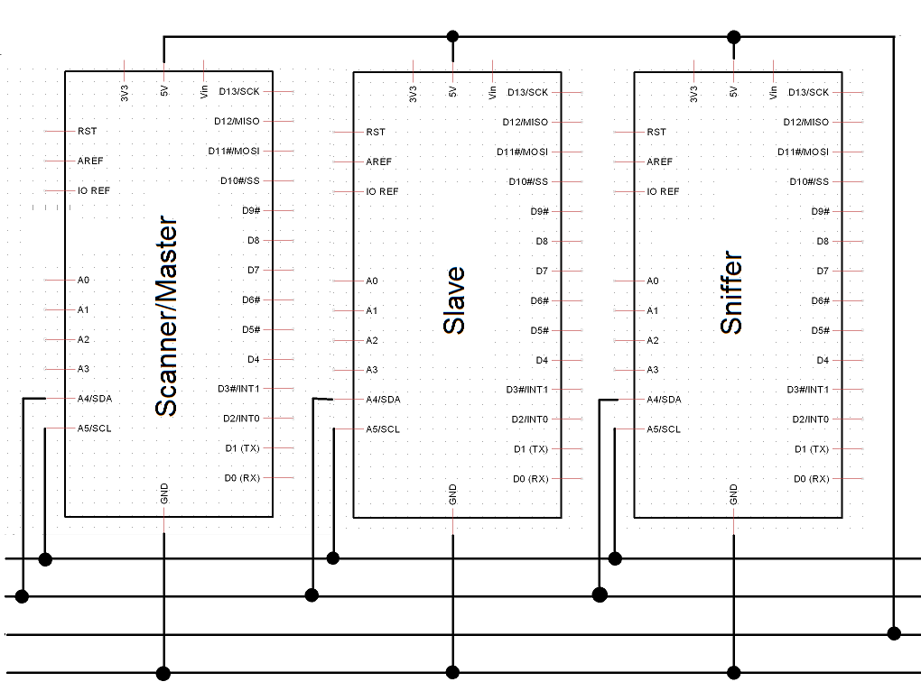
To use it you have to connect SDA and SCL to A4 and A5 as if it were a master or a slave. (Actually, if you do not want to use A4 and A5, you can use another pair of pins, but they must be part of the same port, and this port should not be used by other software.)
Before connecting anything, make sure you have installed level shifters in case you are mixing 5V and 3.3V devices. The default clock rate is 100 kHz, but it works fine even with a clock rate of 400 kHz. (As the Nyquist-Shannon theorem told us, you always need to sample at least with twice the frequency of the signal you want to analyze.) The two assembler statements need just 1 + 2 cycles. At F_CPU = 16 MHz it gives a sampling rate of 5.33 MHz that is more than sufficient. But it also works using a common C loop. The only trick is to devide sampling and decoding in two separate parts.
/*
  I2C sniffer
*/

#define ASM

const byte SDA_mask = 0x10; /* A4 */
const byte SCL_mask = 0x20; /* A5 */
const byte bothHigh = SDA_mask + SCL_mask;
char wr[] = "WR";

void setup() {
  Serial.begin(115200);
  Serial.println(__FILE__);
  Serial.println("SCL SDA");
}

void loop() {
  /* wait for start: */
  while (PINC == B00110000);
  /* now scan: */
  /* could be extended up to 1500 */
  const int N = 500 - 1;
  byte b[N];
  cli();
#ifdef ASM
  /* do not modify if you do not know what you do */
  asm volatile(
    ".rept %[count]\n"  // repeat (count) times:
    "in r0, %[pin]\n"   // read the port input register
    "st Z+, r0\n"       // store in RAM
    ".endr"
    ::      "z" (b), // Pointer register pair Z z (r31:r30)
    [count] "i" (sizeof b),
    [pin]   "I" (_SFR_IO_ADDR(PINC))
    : "r0"
  );
#else
  for (int i = 0; i < N; i++) b[i] = PINC;
#endif
  sei();
  Serial.println("0.1 0.1"); /* start mark */
  byte sclPrev = 0;
  byte sclCnt = 0;
  byte adr = 0;
  byte data = 0;
  for (int i = 0; i < N; i++) {
    byte scl = bitRead(b[i], 5);
    byte sda = bitRead(b[i], 4);
    char out[] = "2 0";
    if (scl) out[0]++;
    if (sda) out[2]++;
    Serial.println(out);
    /* D E C O D E  the first two bytes */
    /* to be printed in the headline of the Serial Plotter */
    /* on rising clock: */
    if (scl > sclPrev) {
      sclCnt++;
      switch (sclCnt) {
        case 2 ... 9: adr = adr * 2 + sda; break;
        /* 10 = ACK/NACK */
        case 11 ... 18: data = data * 2 + sda; break;
      }
    }
    sclPrev = scl;
  }
  Serial.print("SCL SDA__adr=0x");
  if (adr < 32) Serial.print(0);
  Serial.print(adr / 2, HEX);
  Serial.print("_");
  Serial.print(wr[adr & 1]);
  Serial.print("_data=");
  Serial.println(data);
}
Actually, you have to use the Serial Plotter of the "old" IDE to see the results. The decoded values will be plotted in the headline of the plotter.
The bad news of the story is: it did not work with all the Arduino UNOs in my box. The older ones passed the test, but half of the newer ones didn't, no matter if it were DIL-28 or SMD type. Some UNOs were labelled 328PB (note the 'B'), and none of them worked. Neither did the ATmega2560s.
This problem could be solved easily- The reason is that pins A0 to A3 all belonging to Port 'C' are unused in this project, and as they are not connected to anything they might be read as '0' or occasionally as '1', so the comparison at the beginning of the loop function will never become false. Three ways to solve it:
1. by adding some 'hardware': connect A0 -A3 to GND or by software:
2. insert DDRC = B00001111; in the setup function or
3. replace while (PINC == scl_sda); by while ( (PINC & scl_sda) == scl_sda);, which unfortunally slows down the execution of the while-loop.
Apparently, on some boards or inside some chips the wires are so close to each other that the capacitance between that lines gives unwanted signals to unconnected pins. This fix also works for the ATmega328PB. For the ATmega2560, you must replace PINC by PINF.
If you don't need to see the graphics, here is a much shorter version showing the results on a TM1650-controlled 4-digit LED display:
/*
  I2C sniffer
*/
#include <TM1650.h>
/* you can use any two pins except port C */
/* TM1650-CLK, -SDA: */
TM1650 leds(12, 13);
byte S = B01101101;
byte n = B01010100;
byte I = B00110000;
byte F = B01110001;
byte A = B01110111;
byte EQ = B01001000;

const byte sda = 0x00; /* A0 */
const byte scl = 0x01; /* A1 */
const byte scl_sda = (1 << sda) | (1 << scl);

void setup() {
  Serial.begin(9600);
  Serial.println(__FILE__);
  leds.display(0, S);
  leds.display(1, n);
  leds.display(2, I);
  leds.display(3, F);
  delay(1000);
}

void loop() {
  /* wait for start: */
  while (PINC == scl_sda);
  /* now scan: */
  const int N = 500;
  byte b[N];
  cli();
  for (int i = 0; i < N; i++) b[i] = PINC;
  sei();
  byte sclPrev = 0;
  byte sclCnt = 0;
  byte adr = 0;
  for (int i = 0; i < N; i++) {
    byte sdaBit = bitRead(b[i], sda);
    byte sclBit = bitRead(b[i], scl);
    /* on rising clock: */
    if (sclBit > sclPrev)
      switch (sclCnt++)
      case 1 ... 7: adr = adr * 2 + sdaBit;
    sclPrev = sclBit;
  }
  /* user-defined codes: */
  leds.display(0, A);
  leds.display(1, EQ);
  /* library-defined codes: */
  leds.display(2, leds.coding(adr / HEX));
  leds.display(3, leds.coding(adr % HEX));
}
So why did I specify "UNO R3"? The reason is, access to controller port via "PIN" commands are much faster than digitalRead(). And with the R4 you do not have any port accesses. So it only supports I2C sniffing up to a clock rate of 100 khz.
Version for Plug-and-Make Kit with UNO R4 WiFiWith the WiFi board you have two I2C buses. I connected two Qwiic together.
The right board is working using an SHT41 Humidity and Temperature sensor. The left one is the sniffer. Only the SCL1, SDA1, and GND pins are connected, never connect Vcc pins, neither 5 volts or 3.3 volls.
/*
  I2C sniffer R4
  in case you cross platforms
  you have to use level-shifters
  works only up to a clock rate of 100 kHz
  R4 is just fast enough to decode 100 kHz
*/


#define USE_WIRE1

#ifdef USE_WIRE1
/* Qwiic, 3.s volts */
int sdaPin = 27;
int sclPin = 26;
#else
/* standard, 5 volts */
int sdaPin = SDA;
int sclPin = SCL;
#endif

void setup() {
  Serial.begin(115200);
  Serial.println(__FILE__);
  Serial.println("SCL SDA");
}

int get_I2C_bus() {
  return digitalRead(sclPin) * 2 + digitalRead(sdaPin);
}

void loop() {
  /* wait for start: */
  int scl_sda;
  do {
    scl_sda = get_I2C_bus();
  }
  while (scl_sda > 2);
  const int N = 512; /* include: 8 * 8 * 8 */
  /* now scan: */
  byte scl[N];
  byte sda[N];
  int i = 0;
#include "sample1.h" / increments i`*/
  Serial.println("0.1 0.1"); /* start mark */
  byte sclPrev = 0;
  byte sclCnt = 0;
  byte adr = 0;
  char wr = 'W';
  byte data = 0;
  for (int i = 0; i < 499; i++) {
    /* send to the plotter: */
    char out[] = "2 0";
    if (scl[i]) out[0]++;
    if (sda[i]) out[2]++;
    Serial.println(out);
    /*
      D E C O D E  the first two bytes
      to be printed in the headline
      of the Serial Plotter
      check on rising clock:
    */
    if (scl[i] > sclPrev) {
      switch (sclCnt++) {
        case 1 ... 7: adr = adr * 2 + sda[i]; break;
        case 8: if (sda[i]) wr = 'R'; break;
        /* 9 = ACK/NACK */
        case 10 ... 17: data = data * 2 + sda[i]; break;
      }
    }
    sclPrev = scl[i];
  }
  Serial.print("SCL SDA__adr=0x");
  if (adr < 16) Serial.print(0);
  Serial.print(adr, HEX);
  Serial.print("_");
  Serial.print(wr);
  Serial.print("_data=");
  Serial.println(data);
}
The code uses some include files which are not shown. I put the complete R4-version into the attachments.
And this is what you get:
Note that sampling is so slow that most of the sampling array is wasted.
Update: new version availableThis makes it more easy to demonstrate what goes on on the I2C bus. The new version (see attachments) also indicates the boundaries (green) of the transmitted bytes.
Note that the bus also include the power lines. You only connect the sniffer to your PC and observe the Serial Plotter (baudrate = 115200).
From left to right: the master keeps on sending ASCII strings to the slave. The slave accepts the data but does nothing. The sniffer continuously reads the signals and decodes them. You also might use an Arduino UNO R4 WiFi for the sniffer.
Checking the maximum Sampling FrequencySome simple experiments checking the maximum sampling frequency:
I used a square-wave generator and this simple sketch
/*
  check maximum sampling frequency
*/

void setup() {
  Serial.begin(115200);
  while (!Serial);
}

void loop() {
  const int N = 1500;
  byte b[N];
  for (int i = 0; i < N; i++)
#ifdef __AVR__
    b[i] = PINC;
#else
    b[i] = digitalRead(A5);
#endif
  byte prev = 0;
  int count = 0;
  for (int i = 0; i < N; i++) {
    byte act = b[i];
    if (act > prev) count++;
    prev = act;
  }
  Serial.println(count);
}
:And this were my results
UNO R3 and digitalRead: up to 100 kHz
UNO R4 and digitalread: up to 320 kHz
UNO R3 and Port reading: up to 830 kHz.


Comments
Please log in or sign up to comment.