


This Journey can take you a head toward the wireless communication and the automatic control techniques that may help you start your great projects. It also can provide you with some important commands and processes that everyone can follow and apply then eventually be a creative one.
At the first, I going to explains some important AT command that Arduino Libraries used such as the great GSM library. You may wonder why to understand the AT Command while there is a helpful and great library can every used.
So Why AT command ?!.
I can say that there is a great library and easy to use, but we can't ignore the size of a program while including more than one library in one multi functions great program. The great program can become not stable and heavy in hex file result in poor in performance and mistakes could occurred while operating that great program.
On the other hand, AT command is much lighter, faster, and Errors can be easily detect beside a general purpose famous ("Software Serial Library")that can combine with other libraries in more efficient way. The only challenge is to be considering how much delay time each Command need to execute probably. This all information can be found in the Quectel M10 Data sheet.
Quectel M10 At command file is the only document you need in order to start write your own program for your great project. I`m highly recommend you going through the PDF file, Its has such a valuable information I hope you like.
If you understand what going on here, I expect you to have the ability to make a smart home, some security and safety applications, real time monitoring systems, wireless control systems. And you may create your cool project that I did not think about. Please make cool things and share them so we can learned more.
In this Journey I will cover the Arduino GSM shield in this Five Areas:
- Making a real-time GPS Tracker over the internet and Display GPS data on Google Maps.
Also, I will provide you by a quick guide for getting a free API`s key that I used to accomplish and test the Arduino GSM Shield which you can also get and use for your project for free.
Step 1: Components Required_Hardware_
- Arduino GSM Shield 2.
- Arduino Uno OR Arduino Mega 2560/ADK.
- Breadboard/ Jumper Wires.
- Adafruit Ultimate GPS Breakout.
- Waterproof GPS Active Antenna.
- Solar Panel 6W / 6V OR 9W / 6V.
- Lithium Ion Battery Pack.
- Lithium Ion/Polymer Charger.
- 5V USB Boost.
- Power Adapter. ( Optional you can use instead of the solar system).
- Sim Card !!!. ( Depends on your country).
_ Software_
- Arduino IDE.
- Terminal Emulator. ( you can download OR use any other program you like).
- Thing speaks account + API`s Keys.(its free see next guide).
- Google Maps JavaScript API.(its free see next Step).
- Internet Browser!! (The One you use know).
_Libraries required_
Step 2: The Arduino GSM Shield !! (Overview)Description
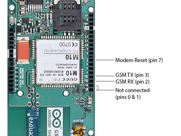
The Arduino GSM Shield allows an Arduino board to connect to the internet, make/receive voice calls and send/receive SMS messages. The shield uses a radio modem M10 by Quectel (datasheet). It is possible to communicate with the board using AT commands. The GSM library has a large number of methods for communication with the shield. The shield uses digital pins 2 and 3 for software serial communication with the M10. Pin 2 is connected to the M10’s TX pin and pin 3 to its RX pin. See these notes for working with an Arduino Mega, Mega ADK, or Leonardo. The modem's PWRKEY pin is connected to Arduino pin 7. The M10 is a Quad-band GSM/GPRS modem that works at frequencies GSM850MHz, GSM900MHz, DCS1800MHz and PCS1900MHz. It supports TCP/UDP and HTTP protocols through a GPRS connection. GPRS data downlink and uplink transfer speed maximum is 85.6 kbps. To interface with the cellular network, the board requires a SIM card provided by a network operator. See the getting started page for additional information on SIM usage. The most recent revision of the board uses the 1.0 pinout on rev 3 of the Arduino Uno board.
Power requirements
It is recommended that the board be powered with an external power supply that can provide between 700mA and 1000mA. Powering an Arduino and the GSM shield from a USB connection is not recommended, as USB cannot provide the required current for when the modem is in heavy use. The modem can pull up to 2A of current at peak usage, which can occur during data transmission. This current is provided through the large orange capacitor on the board's surface.
On board indicators
The shield contains a number of status LEDs:
On: shows the Shield gets power.Net: blinks when the modem is communicating with the radio network.
- Status: turns on to when the modem is powered, and data is being transferred to/from the GSM/GPRS network.
For more Information see Getting Started with the Arduino GSM Shield
Also you can see GSM library.
The datasheet for the Quectel M10 modem can be found here
Step 3: Getting Started!We will use two methods:
- The Terminal Emulator. (brief introduction see pics)
- Using Arduino code (Uno/Mega) compatible.
Now we will prepare the Arduino board for communicating with the PC by UART protocol. Emulate a second serial port (UART) using software on the digital pins D2 and D3 and patch through all the communication between this second software serial port and the actual hardware serial port. By doing this, all the data coming from the computer (connected to the actual hardware UART) would be relayed as is to the GPRS Shield (connected to software UART).
- Run Arduino IDE 1.0 or later
- Download the the terminal emulate codes and upload to your arduino.
Now all done to start use Arduino with either method.
1. Using AT commands Via
- Open your favorite serial terminal software, choose the COM port for Arduino and press connect.
- Press and hold the power button a short while (Over 3 seconds) on the GMS Shield to turn it on.
- Now, type and send "AT" (without the quotes) followed by carriage return (enter key) to the Arduino board. The GPRS Shield should respond by sending back an "OK". This would mean that you have been able to successfully setup your GPRS Shield can now play around with various AT Commands.
Sending a text message (SMS) –AT COMMAND
- Install GSM shield in Arduino board and connect power cord.
- Open your serial monitor program (I use SSCOM)
- Through your serial terminal software, send AT+CMGF=1 and press the Enter key. The GPRS Shield can send SMSes in two modes: Text mode and PDU (or binary) mode. Since we want to send out a human readable message, we will select the text mode. The GPRS Shield will respond with an OK.
- Send AT+CMGS="+966XX6541231" and press the Enter key (include the quotes). This will instruct the GPRS Shield to start accepting text for a new message meant for the phone number specified (replace the number with the phone number of the target phone). The GPRS Shield will send a > signaling you to start typing the message at the last of the massage type "*" (without the quotes).
Make a Call –AT COMMAND
- Type ATD +966566996070; // Write phone number you want to call
- Respond OK, you will receive a call.
- Type ATH to end a call.
I assume that you already have a thingspeak account. If not then visit and create your account. Then, follow the below process:
- Got to"Channels" and click on "New Channel" as shown in the image1.
- Then Enter following details as shown in the image2.
- Scroll down and hit "Save Channel" as shown in the image3.
- Now your channel has been successfully created. Click on your created channel and then click on "API Keys" tab and you will get the following details: as shown in the image4.
- Channel ID
- Write API Key
- Read API Key
Which will be used by us for writing, reading the data on/from thingspeak server. So copy and pasted it on a notepad file and keep it ready.
Step 5: Getting the Google Maps API Key !!Preview
In this Step, we are going to get the json data from the thingspeak server and parse it using HMTL and javascript to show it in Google Maps along with a marker. I hope that you already have a google or gmail account. Follow the below steps to get the Google Maps API key which will be used in our code to get the json data and show it in the marker on Google Maps.
- Go to HERE and click on "Get A Key" on the top right corner as shown in the below image.
- Now Click on "Select or Create Project" in the dialog box which appears after clicking on "Get A Key" as shown in image1.
- Select the "Create a new project" from the list as shown in image2.
- Give a name to your project and click on "Enable API"as shown in image3.
- Now you will get an API Key in a text box. Click on "copy clipboard" icon (the file on file icon) and hit "Finish". You now have Google Maps API key which you can use in your HTML code to show map.as shown in image.
- Now copy and paste the following file in notepad++ and save it as "index.html".
See The File HERE
Now replace the following credentials: as shown in image5.
- Your Google API key
- Your Thingspeak Read API key
- Your Thingspeak Read API Key
- Your Thingspeak Channel ID
- Your Thingspeak Channel ID
- GPS tx/rx to the arduino digital pins 8/9
- The devices to control to the arduino digital pins 8 to 12
- They all subject to change as you want, but you must change also in the arduino sketches as well.
GO back to step 4 and 5 if you have done all require thing you can know use the coming program to display a real time GPS Location on Google maps.
Now double click on your webpage "index.html" that you already saved on step 5 and wait for some time. It will take some time to load the map and marker. If you have done everything right, then you will get the following output.
<p>/********************************************************************<br> *  AltSoftSerial always uses these pins for Serial communication:  *
*                                                                  *
* Board          Transmit  Receive   PWM Unusable                   *
* -----          --------  -------   ------------                   *
* Teensy 3.0 & 3.1  21        20         22                         *
* Teensy 2.0         9        10       (none)                       *
* Teensy++ 2.0      25         4       26, 27                       *
* Arduino Uno        9         8         10                         *
* Arduino Leonardo   5        13       (none)                       *
* Arduino Mega      46        48       44, 45                       *
* Wiring-S           5         6          4                         *
* Sanguino          13        14         12                         *
*********************************************************************/</p><p>#include
#include
#include
TinyGPSPlus gps;
AltSoftSerial ss;
SoftwareSerial GPRS(2, 3);</p><p>unsigned char buffer[64]; // buffer array for data recieve over serial port
int fixed = 0;
int count = 0;   // counter for buffer array
//int led = 13;
int setupStep = 0;
double longi = gps.location.lng();
double lati = gps.location.lat();</p>
<p>void setup()<br>{

ss.begin(9600); //Start GPS
GPRS.begin(9600);               // the GPRS baud rate
Serial.begin(19200);             // the Serial port of Arduino baud rate.
delay(10000);
}</p><p>void loop() {</p><p>   longi = gps.location.lng();
lati = gps.location.lat();
GPSCord();
Send_pubnub();
delay(1);
setupStep = 0;
}</p><p>void clearBufferArray()              // function to clear buffer array
{
for (int i = 0; i < count; i++)
{
buffer[i] = NULL; // clear all index of array with command NULL
}
}</p>
<p>void GPSCord(){<br>  while (ss.available() > 0)
gps.encode(ss.read());</p><p>  if (gps.location.isUpdated())
{
fixed = 1;
//  Serial.print("LAT="); Serial.print(gps.location.lat(), 6);
//  Serial.print(" LNG="); Serial.println(gps.location.lng(), 6);
}</p><p>  if(fixed ==0)
{
//  digitalWrite(led, HIGH);   // turn the LED on (HIGH is the voltage level)
//  delay(300);               // wait for a second
//  digitalWrite(led, LOW);    // turn the LED off by making the voltage LOW
//  delay(300);
// Serial.print("NO GPS Signal Detected");
}
if (gps.altitude.isUpdated())
{
//Serial.print("Altitude:");
//Serial.println(gps.altitude.meters());
}
}</p>
<p>void ConnectToInternet(int step) {</p><p>  int delayT = 1000;</p><p>  if (step == 0) {
GPRS.println("AT");
delay(delayT);
}</p><p>  if (step == 1) {
GPRS.println("AT+CPIN?");
delay(delayT);
}</p><p>  if (step == 2) {
GPRS.println("AT+CREG?");
delay(250);
}</p><p>  if (step == 3) {
GPRS.println("AT+CGATT?");
delay(delayT);
}</p><p>  if (step == 4) {
GPRS.println("AT+QIDEACT");
delay(delayT);
}</p><p>  if (step == 5) {
GPRS.println("AT+QISTAT=?");
delay(250);
}</p><p>  if (step == 6) {
GPRS.println("AT+QIMUX=0");
delay(250);
}</p><p>  if (step == 7) {
GPRS.println("AT+QIREGAPP=\"zain\","",""");
delay(delayT);
}</p><p>  if (step == 8) {
GPRS.println("AT+QIACT");
delay(delayT);
}</p><p>  if (step == 9) {
GPRS.println("AT+QILOCIP");//get local IP adress
delay(250);
}
if (step == 10) {
GPRS.println("AT+QIPROMPT=0"); //No prompt ">" and show "SEND OK" when sending successes
delay(delayT);
delay(250);
}</p><p>  if (step == 11) {
GPRS.println("AT+QIOPEN=\"TCP\",\"184.106.153.149\",\"80\"");
delay(delayT);
delay(2000);
}</p><p>  if (step == 12) {
GPRS.println("AT+QISEND");
delay(delayT);
// delay(2000); //More delay time could be require depend on network
}
if (step == 13) {
String str="GET <a href="https://api.thingspeak.com/update?api_key=206IRORJO5AHJZUN&field4="> https://api.thingspeak.com/update?api_key=206IROR...</a> + String(lati,6)+ "&field5=" + String(longi,6);
GPRS.println(str);
delay(delayT);
//delay(2000);//More delay time could be require depend on network
}
if (step == 14) {
GPRS.println((char)26);// ASCII code of CTRL+Z
GPRS.println();
delay(delayT);
//delay(2000);//More delay time could be require depend on network
}
setupStep++;
}</p>
You can have HERE
The HTML index HERE
Step 8: ConclusionI hope you enjoy This journey and If you have any Question you are welcome to ask.
Have fun making great project!!
Please Share your great project and lets learn more!

Comments
Please log in or sign up to comment.