


Hardware components | ||||||
| × | 1 | ||||
| × | 1 | ||||
| × | 1 | ||||
Software apps and online services | ||||||
 |
| |||||
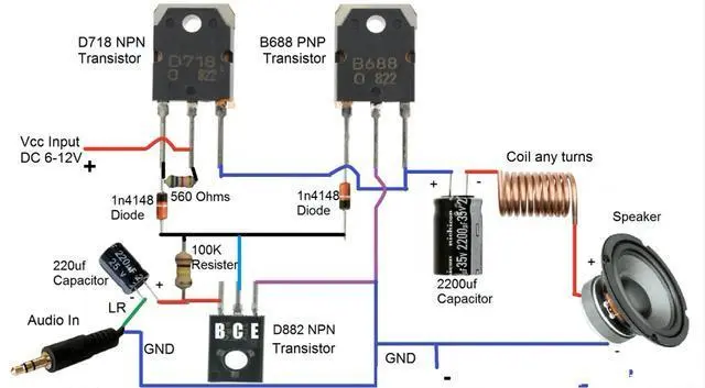
Power amplifiers come in many forms, ranging from lightweight to large and bulky. But the basic principle remains unchanged. Today, we are building a simplest power amplifier with one-stage drive. Although the circuit is simple, it can be used in practical applications.
Step1. Prepare an aluminum heat sinkFirst prepare an aluminum heat sink. Since the power is not very high, a thickness of about 2MM is enough. Then fix D718 and B688 on the aluminum heat sink.
Step2. Note that since the back of the power tube and the collector of the triode are connected, an insulating mica sheet must be placed to prevent fireworks when the power is turned on. The picture above shows two IN4848 diodes, which are connected to the base of D718 in the forward direction and the base of B688 in the reverse direction. Because D718 is NPN type, it can only be turned on by forward bias, while B688 is the opposite.
Next, connect a wire to the other ends of the two diodes. Used to transmit audio excitation signals.
Step5. Connect a 560 ohm resistor across the B and C terminals of D718 to provide a bias voltage to turn on D718.
Step6. Also weld a 100K resistor between the B and C terminals of D882 to provide bias voltage. Make it conductive.
Step7. Weld the positive electrode of a 16V 220UF capacitor to the base of D882 to transmit the audio signal input.
Step8. Use the yellow wire to connect the D718 and B688 emitters, which are used as audio power output to drive the speaker to produce sound.
Because it is powered by a single power supply, the output terminal has voltage and cannot be directly connected to the speaker. A 25V 2200UF is used to isolate DC. Use a signature pen as the core, wind the copper wire around 20 turns, and turn it into an inductor coil, which is connected to the front end of the speaker to filter out excess clutter.
After the inductor, connect the positive electrode of the speaker, and the negative electrode of the speaker is connected to the collector of B668 through a black wire as a common ground. and connected to the D882 emitter. Find an audio signal cable with a 3.5 plug, and connect RL in parallel to the negative pole of the 220UF capacitor. The negative electrode is connected to the common ground terminal of the B688 collector. Find a 6-12V DC power supply, connect the positive terminal of the power supply to the collector of D718, and the negative terminal to the common ground of the collector of B688.
Then plug it into the headphone jack of your phone and you can enjoy music. Although the circuit is simple and the sound quality is average, this is a circuit that can be used in practical applications.

Comments
Please log in or sign up to comment.