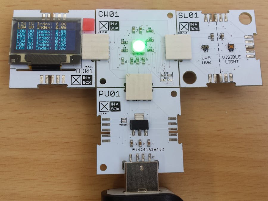
With absolutely no soldering and wiring, I built this project which indicates the Ultra Violet Index and displays a message inferring the severity of the ultra violet rays. E.g., when the UV Index is between 0 and 3, an OLED display will show "LOW UV Index: 0.04" with an accompanying green LED.
- 0 - 3 -> LOW -> Constant Green LED
- 3 - 6 -> MODERATE -> Flashing Green LED
- 6 - 8 -> HIGH -> Red LED
- 8 - 11 -> VERY HIGH -> Flashing Red LED
- 11 + -> EXTREME -> Fast Flashing Red LED
More information can be found on Wikipedia Ultra Violet Index regarding UV Index.
This simple project can serve as a reminder to exercise precaution before stepping in the sunlight.
Program and BuildStep 1: Software SetupDownload the following libraries and add them to the Arduino IDE Libraries. Also download the board and follow the instructions that accompany it.
- xSL01 library
- xCore library
- xOD01 libary
- ESP8266 Board
After installing the board, select the "Generic ESP8266 Module" as shown below and replicate other parameters under Tools. Be sure to select the correct COM port.
Connect the CW01 and IP01 using the XC10 Bus connectors by simply clicking them together. Ensure that the ☒CHIP identification names are orientated in the same direction as shown below (applies to all ☒CHIPS). Insert the IP01 along with the CW01 into an available USB port on your computer. Download or copy and paste the code below into your Arduino IDE. Compile the code first to ensure no errors are apparent. After compilation you may upload the code to your board. Once uploaded unplug the board from the USB port and disconnect IP01 from CW01 by simply pulling them apart. IP01 is no longer needed. Consult the hardware requirements for a description of each ☒CHIP.
You may now connect the OLED Display (OD01) and the UV Sensor (SL01) using XC10 bus connectors as as illustrated below.
You may use any of the following options to power up your UV Index project:
- PU01 connected to a power bank or similar
- PB02 with a coin cell battery
- PB01 with AA batteries
Connect any one of them to CW01. I've used a PU01 with a power bank as shown in the image below.
When indoors with no direct sunlight shining on SL01, you should get approximately a reading of 0 with a LOW UV Index message. If you take the sensor outside and place it in the sunlight, the RGB LED will flash according to the UV Index measured and indicate the UV Index on the OD01 OLED Display. Watch the video below to see the build.


Comments
Please log in or sign up to comment.