

Hardware components | ||||||
_ztBMuBhMHo.jpg?auto=compress%2Cformat&w=48&h=48&fit=fill&bg=ffffff) |
| × | 1 | |||
 |
| × | 4 | |||
 |
| × | 4 | |||
 |
| × | 1 | |||
 |
| × | 1 | |||
 |
| × | 5 | |||
 |
| × | 1 | |||
 |
| × | 1 | |||
Software apps and online services | ||||||
 |
| |||||
| ||||||
Hand tools and fabrication machines | ||||||
 |
| |||||
 |
| |||||
In this project we use an Arduino UNO to build a 4 bit Binary counter. We have been dealing with Decimal numbers all our lives & a sudden change to binary during our High school/ College days can put off some students specially in subjects like Digital Logic Design, Switching Theory & Boolean algebra for the sake of gaining clarity in those subjects one can build this fun project to see the theory unravel.
WHAT DOES IT DO?This project as the name suggests is a counter which merely counts from zero to fifteen while representing them in 8-4-2-1 code or BINARY code. Each LED Glows up to show the place value & by adding all the individual digits of the glowing LEDS one can find out the equivalent number in decimal. Still not clear? Take a look at this table to bring more clarity.
So, the leftmost LED (green) is the one which represents the number 1, the RED LED represents the number 2, Yellow represents 4 & BLUE represents 8. Hence, for representing a number 5 we must switch on the Green & Yellow LED( 1 + 4 = 5 ). Now you get the hang of it!
For this project first we shall develop the Code & then simulate it on TinkerCAD (optional) to make sure that everything works fine & then we start with the Hardware.
CODEFor this project the code is fair & square very easy. We begin by declaring the variables for the pins we will be using in the project. Now for control of four LEDS we will be needing 4 pins & those are declared as following. A timr variable is also declared for setting up delay. A counter is initialized.
int pin1=11;
int pin2=10;
int pin3=9;
int pin4=8;
int i=0;
int timr=1000;
All these pins are now declared in the setup() as output pins because well, we will be using them to light up the LEDs by giving output via Arduino.
void setup() {
// put your setup code here, to run once:

pinMode(pin1,OUTPUT);
pinMode(pin2,OUTPUT);pinMode(pin3,OUTPUT);pinMode(pin4,OUTPUT);
}
Now for the counting algorithm, initially we set all the LEDs as low to depict the decimal zero. And we start increasing the counter declared earlier in the code. This counter works on following principle:
count % 2 = 0 for even numbers and 1 for odd numbers.
count % 4 = 2 or 3 when count is a multiple of 2 or 3.
count % 8 = 4, 5, 6, or 7 when count is a multiple of 4, 5, 6, or 7.
count % 16 = 15, 14, 13, 12, 10, 9, 8 for numbers between 8 to 15.
void loop() {
// put your main code here, to run repeatedly:
digitalWrite(pin4,LOW);digitalWrite(pin3,LOW);digitalWrite(pin2,LOW);digitalWrite(pin1,LOW);
delay(timr);
i++;
if((i % 2) > 0) { digitalWrite(pin1, HIGH); } else { digitalWrite(pin1, LOW); }
if((i % 4) > 1) { digitalWrite(pin2, HIGH); } else { digitalWrite(pin2, LOW); }
if((i % 8) > 3) { digitalWrite(pin3, HIGH); } else { digitalWrite(pin3, LOW); }
if((i % 16) > 7) { digitalWrite(pin4, HIGH); } else { digitalWrite(pin4, LOW); }
delay(timr);
}
Now we are ready to upload this code but before that we need to get the hardware setup.
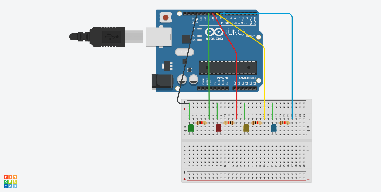
HARDWAREFirstly we need to set the four LEDs on the breadboard (Green, Red, Yellow, Blue) with their respective current limiting resistors on the breadboard. The order of the LEDs can be followed as prescribed for following along.
Now we need to connect the Arduino to power the board & control the LEDs. We will use the pins 11, 10, 9 & 8 as the output pins as described in the source code. Pin 11 is connected to the Green LED, Pin 10 to Red LED and so on. Here the 8-4-2-1 code will stand as follows,
Value 1 - Green LED
Value 2 - Red LED
Value 4 - Yellow LED
Value 8 - Blue LED
The GND pin of the Arduino is connected to the Breadboard to create a common ground which can be used to complete the circuit using small jumper wires.
Once the Code has been compiled & hardware setup we are all ready to connect the Arduino to the PC to power up the project. I have used my PC for powering up the Arduino but a 9V battery can be readily used for the same.
Now all that is left to do is put all these components in a case. I have upscaled a carboard box for the same but have listed a Plastic container which will fit all these components easily. Now all that is left to do is create holes in the box for the LEDs and turn on the Arduino & start learning.
Here is a video to show the working of this project.
I really hope you have enjoyed this small fun project and it works as a base for your further learnings. CHEERS !!


Comments