


Hardware components | ||||||
| × | 2 | ||||
 |
| × | 1 | |||
 |
| × | 1 | |||
 |
| × | 1 | |||
 |
| × | 1 | |||
 |
| × | 2 | |||
Hand tools and fabrication machines | ||||||
 |
| |||||
This project is about a 16 LED controller using 2 shift registers 74595. This project is made in Autodesk Eagle a worldwide used PCB Design software. The components we will use here are:
- Shift Register 74595 - 2
- LED 5mm - 16
- Male Pinheader (6) - 1
- Resistors 10K ohm- 16
- Capacitors 0.1uF - 2
First, open up the Schematic window in Eagle and start making the circuit using the above components and try to use the bus tool as it is easy to read the schematic and easy to find errors if there are any, Make your circuit as given below if you face any problem then don't worry I will provide the schematic in the attachments below for your reference.
Once your schematic is complete run the ERC and check for the errors and eliminate them. After that Go to edit and select the net classes option and select the values for with, drill size, and clearance make sure to make the width of the power lines thicker for better results.
After finishing all these now we can move to the board layout option and start putting the components on the board the board dimensions are 80 X 60 you can measure it using the dimension tool. For making the edges of the board round use the Meander tool and select the edges it will automatically make the changes.
As this is a 2 layer PCB the red color wires represent the wires on the top layer while the blue ones represent the bottom layer wires. Use the Paint roller tool for the perfect alignment of the resistors. You can also see some VIAS for connecting the wires between the top and the bottom layer. After placing all the components and labeling them start the routing process and connect all the components make sure no air wires are left. Now you can apply the polygon on the both top and the bottom sides of the board you can do it easily with the help of the ULP.
After applying the polygon the board will look perfect and nice.
Now run the DRC to check if there is an error in your design or not hopefully you will not get any Errors. I will provide the layout file in the attachment below for your reference. After that click on the manufacturing tab to preview your PCB.
You can change the color of the soldermask by clicking on the configure preview and then select the solder mask color and change it from there.
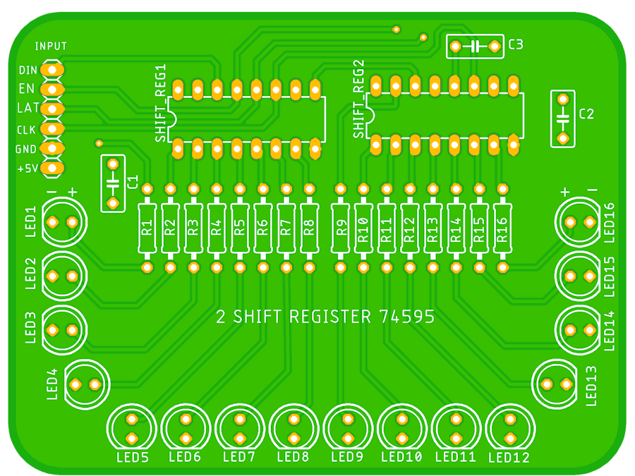
After this generate the Gerber files and send them to any PCB manufacturer to get your PCB and solder your components and connect it with any microcontroller like Arduino to see its working. Your final PCB will look like this :


Comments
Please log in or sign up to comment.