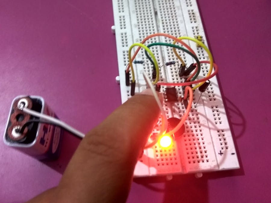
Darkness Detector or Dark Detector is a circuit that detects darkness or absence of light. In this project, we have implemented a simple Darkness Detector Circuit using the simplest of all light sensors: the LDR (Light Dependent Resistor).
Darkness Detector circuits like this can be used in applications where we can automatically turn on lights when it becomes dark.
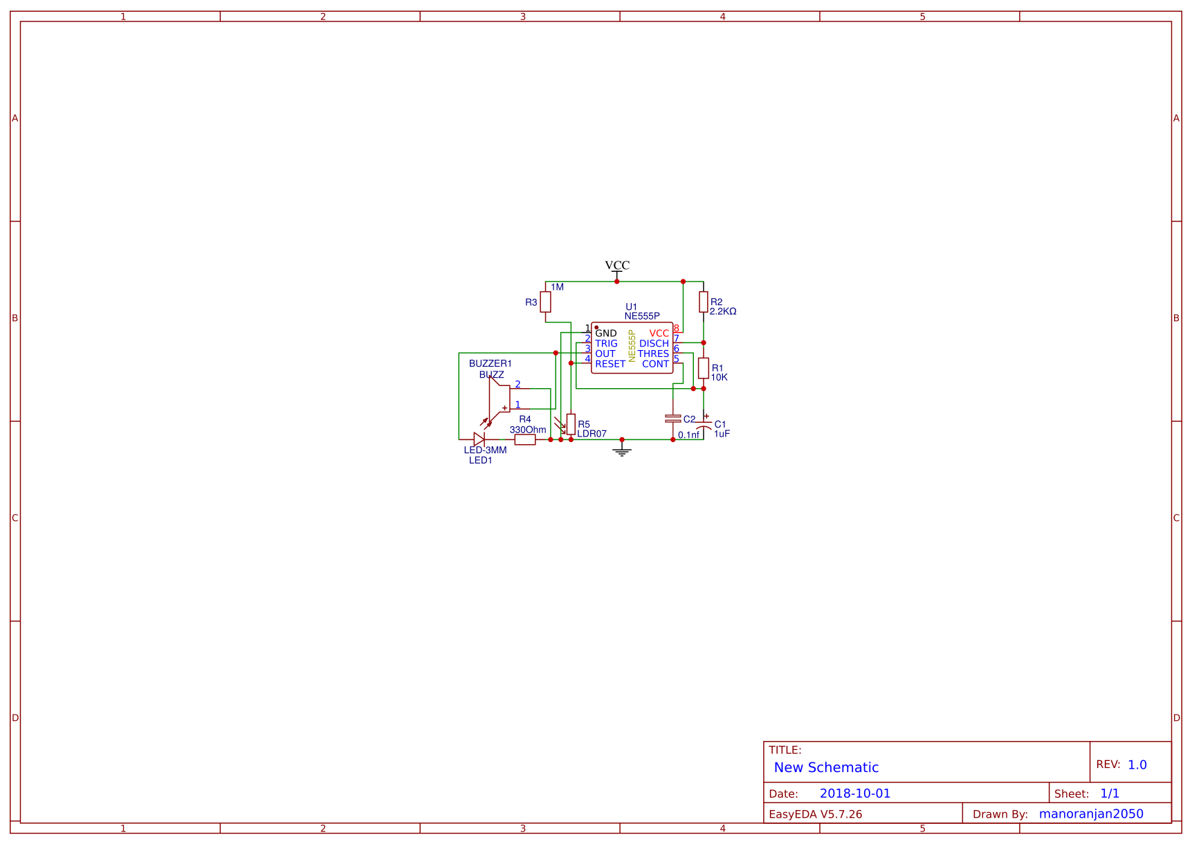
In addition to the LDR, we have also used the good old 555 Timer IC in Astable Mode to generate the required square wave. There are some passive components like capacitor and resistors. We have used a Piezo Buzzer as an alarm to indicate darkness.
The aim of this simple project is to detect darkness with the help of LDR and activate the buzzer And LED.
NOTE: As this is a simple circuit, we haven’t implemented any automatic light on systems but just a buzzer And LED
Components RequiredTo implement this project, we need the following components.
- 1 x 555 Timer IC
- 1 x LDR
- 1 x Piezo Buzzer
- 1 x 10 KΩ Resistor (1/4 Watt)
- 1 x 2.2 KΩ Resistor (1/4 Watt)
- 1 x 1 MΩ Resistor (1/4 Watt)
- 1 x 1 µF Electrolytic Capacitor (50V)
- 1 x 0.1 nF Ceramic Capacitor (Also called 100 pF with code 101)
- 1 x 9V Battery
- 1 x Mini Breadboard
- Jumper Wires
IC 555: 555 Timer is an 8 – pin DIP IC and it is one of the commonly used Timer ICs for different applications like timing, pulse generation, OP – Amps, etc.
The 555 Timer IC is used in this project in its Astable Multivibrator Mode of operation (with a slight modification). The following is the pin diagram of the 555 Timer IC.
LDR (Light Dependent Resistor): LDR or Light Dependent Resistor is one of the commonly used light sensors. In this project, we are using an LDR to detect darkness i.e. when the intensity of light decreases.
- This project can be implemented in applications like automatic switching on of lights when it becomes dark.
- This circuit can be part of a bigger circuit or project like home automation or home security system


Comments
Please log in or sign up to comment.