If you need to control the speed of a DC motor the easiest way to do it is using a transistor.
This is possible thanks to the PWM.
The PWM (Pulse-Width Modulation ) is a signal with a variable duty cycle.
If we use this signal and a transistor we can control the speed of a motor.
Consider this schematic:
In this case the inductor represent the motor. Thanks to the PWM signal DC Motor doesn't feel 12V but the voltage that it feels is proportional to the PWM.
In particular the voltage depends on the duty cycle (δ).
The duty cycle is this:
So it is a number for 0 to 1. But it is often expressed as a per cent so it goes from 0% to 100%.
In the first it is from 0 to 1.
For example with a δ = 0.5 (50%) and Vmax = 12V we have 6V around the motor.
But if δ = 1 (100%) we have 12V around the motor, but δ = 1 means that the signal is always high so it is direct current and we have the maximum power.
HOW DO IT!- Hardware
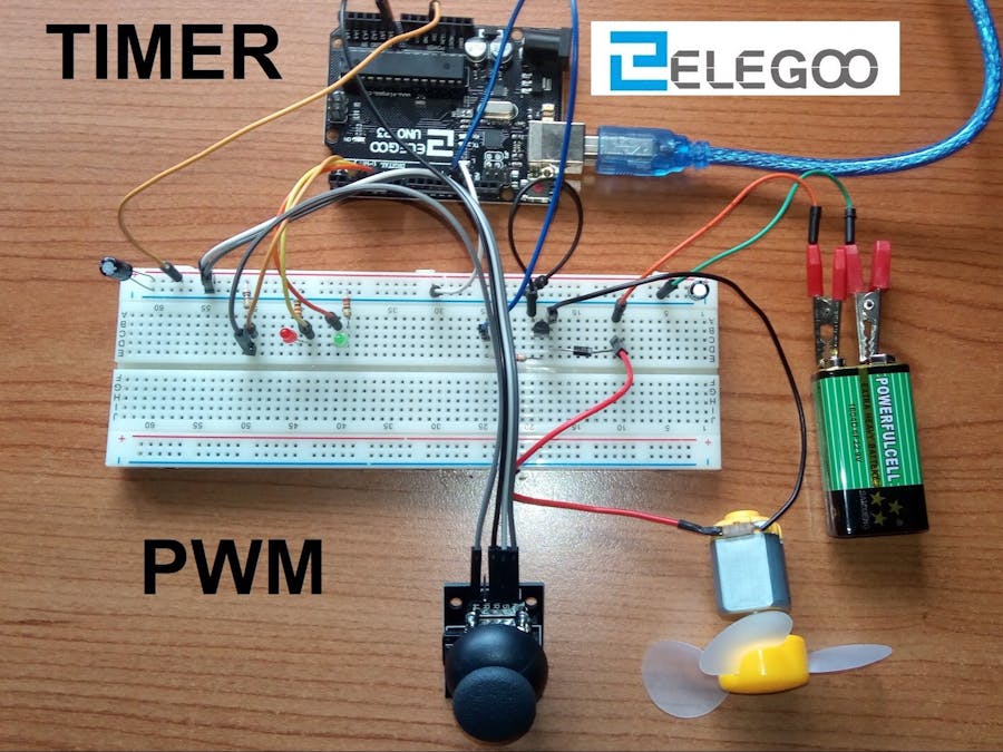
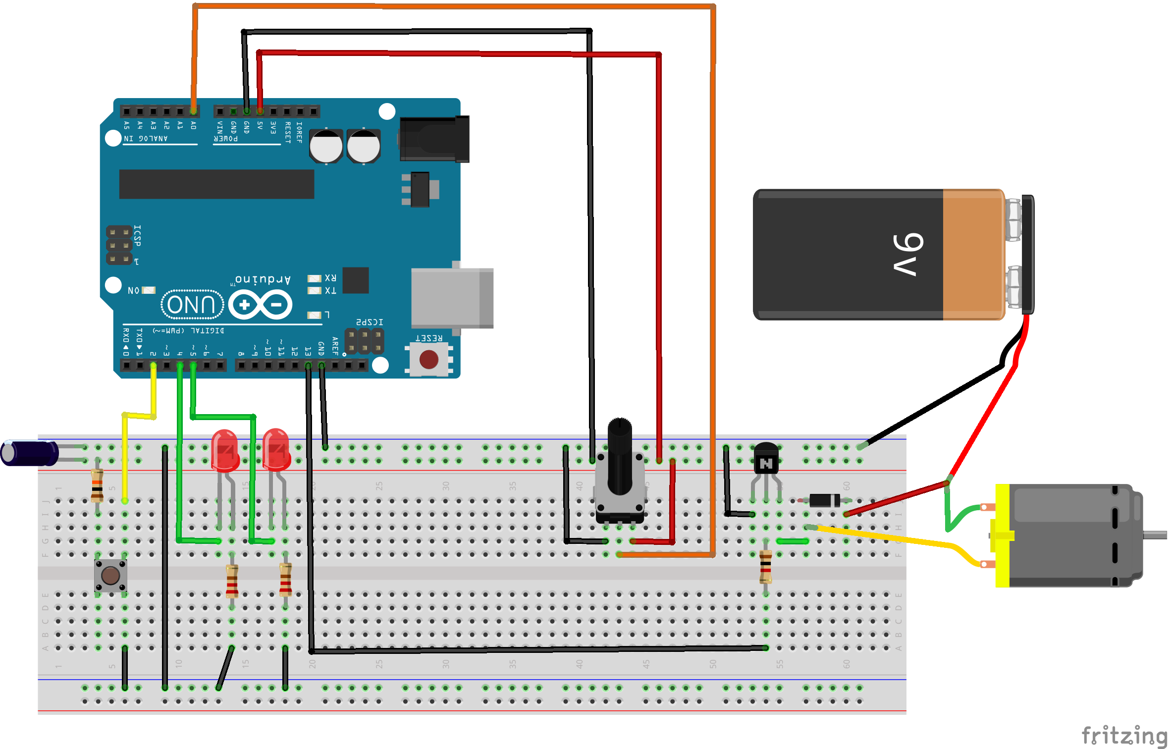
The hardware doesn't need a lot of components. There are:
- 1 Transistor: For a better result it should be an high speed switch transistor (2n2222)
- 1 Diode (D1) in this case is necessary because we use a motor and it is a sort of inductor. In fact when we control an inductor with a square wave the inductor can create some high voltage spikes which can destroy the transistor. The diode removes these spikes.
- 1 Base resistor for the transistor. In this case I use 1KΩ but near values are also good.
- SOFTWARE
In this case we can use the PWM signal of the Arduino but it has got a frequency around 1kHz, so it is better use an higher frequency.
I will use the Internal Timer to make my personal PWM signal.
If you want to know more about Timer watch my project: Internal Timer.
I create a 5kHz PWM from Arduino thank to TIMER0.
 TCCR0A = (1 << WGM01); //Set the CTC mode
 OCR0A = 0x04;          //Value for ORC0A for 2us
 TIMSK0 |= (1 << OCIE0A); //Set the interrupt request
 sei(); //Enable interrupt
 TCCR0B |= (1 << CS01); //Set the prescale 1/8 clock
 TCCR0B |= (0 << CS00);  //Now timer is on
After that I create an ISR ( Interrupt Request Service ) every 2μs.
ISR(TIMER0_COMPA_vect) {   //This is the interrupt request
 timer++;    //+1 every 2 us
 if (timer <= (percent * 2))    // The duty cycle depends on the value
                                // of "percent" which represent the per cent
                                // of duty cylce that we have requested
    digitalWrite(13, HIGH);
 else
    digitalWrite(13, LOW);
 if (timer >= 200) timer = 0;    //Every 200us reset the timer value
}
There will be an external potentiometer which one we can control the value of the duty cycle.
After that we need also a push button to control the state.
In the Elegoo's kit I found a joystic with a push button and two potentiometer so I will use it.
Now the software must do the counts with the reality.
So there are two important restrictions:
- we can't use the complete range of PWM but from 100% to 30% because under 30% the motor will stop.(This depends on the type of motor)
- we must create a function which start the motor without the PWM. For example for 1s the motor run at the highest speed after that we can control it with PWM. That's because we can't think to start the motor with a PWM of 30%, for example.
For these reasons I take out the code from ISR and I control the PWM in the loop() function.
In the ISR I left only timer++.
Complete code below.
This is the final result.


_ztBMuBhMHo.jpg?auto=compress%2Cformat&w=48&h=48&fit=fill&bg=ffffff)


_3u05Tpwasz.png?auto=compress%2Cformat&w=40&h=40&fit=fillmax&bg=fff&dpr=2)
Comments