


Hardware components | ||||||
 |
| × | 1 | |||
| × | 1 | ||||
| × | 1 | ||||
| × | 1 | ||||
Every summer (after planting vegetables in my garden), I was irritated to always go to the basement of my house, so that I could activate the desired zone (garden) on my irrigation controller and had to come back again (once the timer was done) to the basement and set back the controller zone to 'all zone'.
That's when I decided to build my own smart wifi irrigation system controller! I already have a 8 zones sprinkler System (7 for my lawn and 1 for the garden), so this project will focus on the controller using ESP8266 and the PCF8575 that could easily expand your existing configuration up to 16 zones.
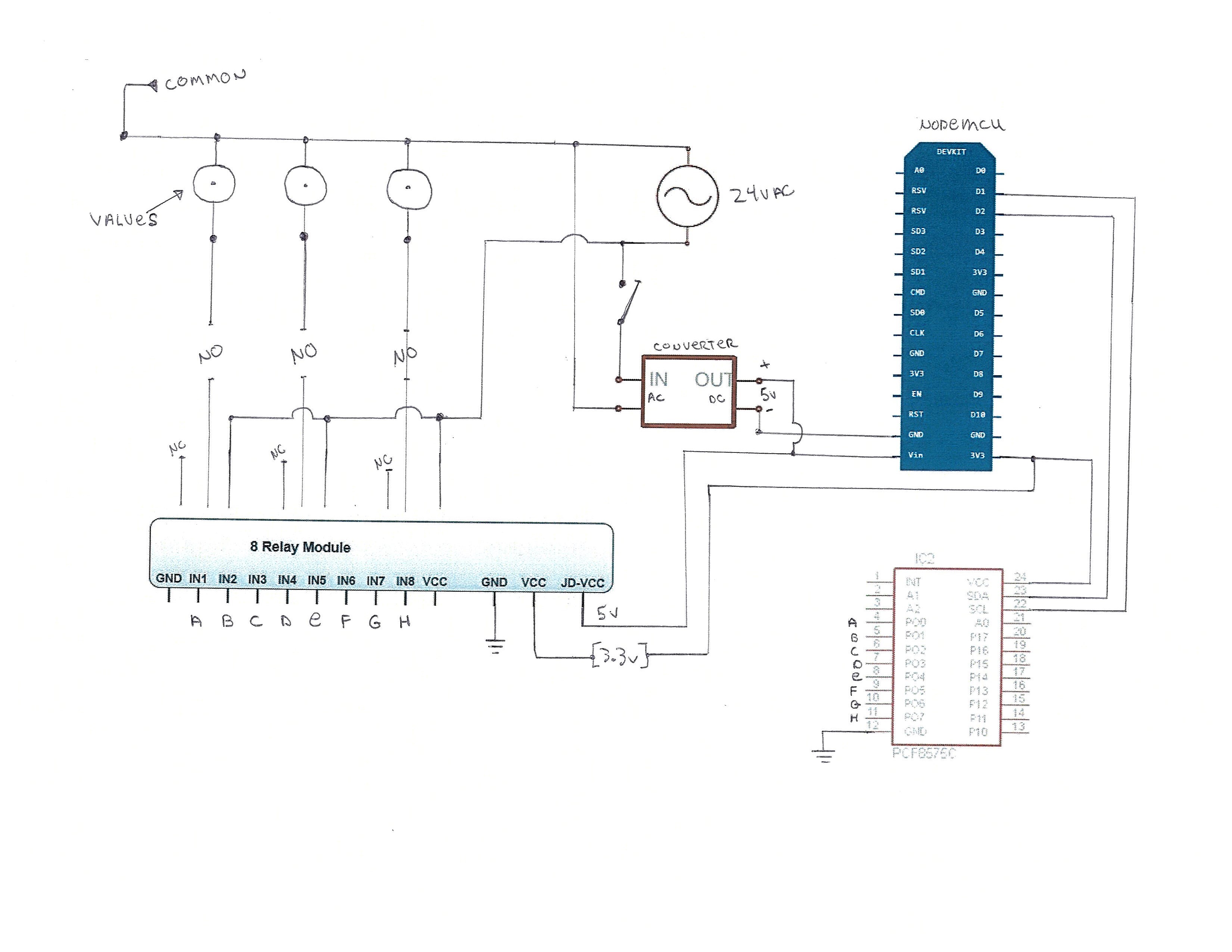
Irrigation system basic functionalityBefore replacing the controller, lets define what is needed. Most irrigation system is powered by 24v AC (controller & solenoid valves) like the one installed at my house. Each valves define an area (Ex.: Zone 1, Zone 2, Zone 3, etc.) and when powered, water start flowing trough the pipes and activate one or multiple sprinklers for water irrigation.
The wires connectivity is as followed. Tie all common wires together (see diagram) and attach (common wires) to ONLY one of the 24vac wire. The other wire from the 24vac will be added to the relay board (see below for detail).
PartsI decided to keep the original power supply of 24v AC and reuse it to power my own controller and the solenoid valves.
This is a AC/DC to DC Step Down Converter - Because I want to use ONLY one power supply (the original 24vAC), its needed to convert the input AC voltage and output (using trim pot) 5v DC to power the electronic components (relay, ESP8266, IO expander) of my controller replacement.
The ESP8266 is the brain of the operations for most of the activities performed (see below), but lacks in IO ports (this is where the PCF8575 shine).
- Fetching the UTC time
- Hosting a web portal
- Activate or stop any zone (valve)
- Switch between manual & automatic mode
The PCF8575 is an IO expander containing 16-bit quasi-bidirectional port. Communication to this chip is done with I2C (only 2 wires needed). What I like about this chip is:
- benefit of using 16 ports (quasi-bidirectional)
- low current consumption with high current drive capability (sink current)
- Operating supply voltage is between 2.5 to 5.5 V
Once the MCU give the signal for a specific zone (valve), it will communicate (through I2C) and activate a port on the PCF8575 to sink current (port = 0V) from the relay pin and activate the relay valve (or zone). The relay will close the circuit and permit power (24vac) from the original power supply into the solenoid valves and since I have 8 valves, 8 relays are needed.
The total cost for all the parts is approximately 35$ (can).
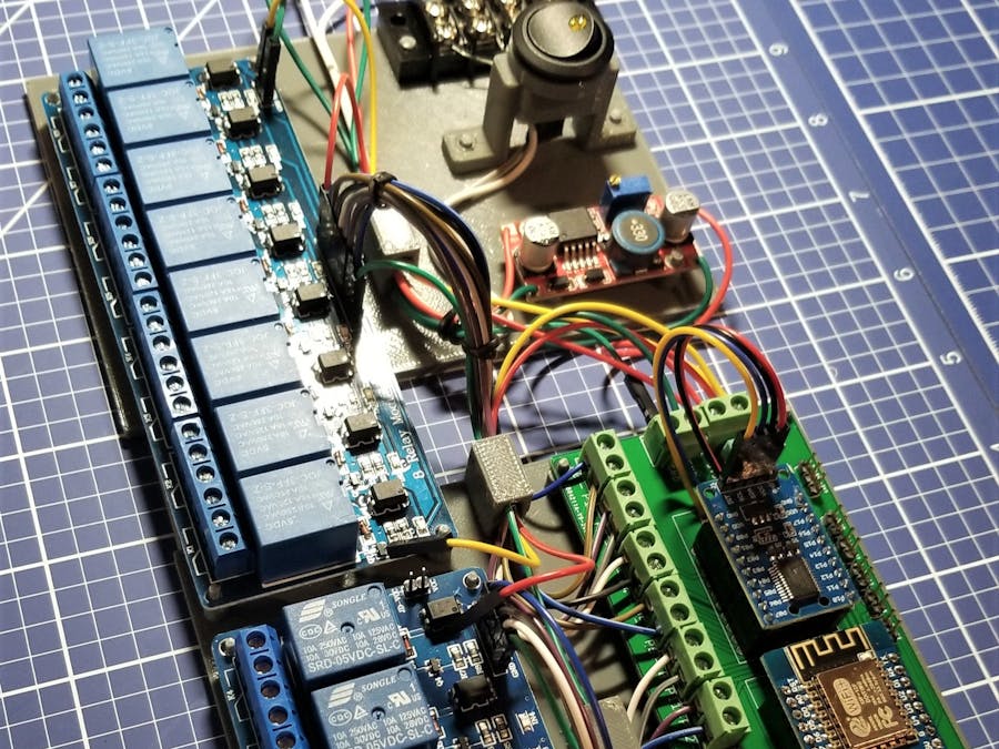
Proof of conceptNow that we have the main components, assemble the electronic parts on a protoboard (from the schematic file). Then start building a program that only communicates with the PCF8575 chip to control the first 2 IO ports. Finally, proceed by adding the relay board and perform test. Validation is done, I'm ready to mount the ESP8266 and PCF8575 on a breadboard.
Final assemblyFinal phase is to assemble all the electronic components (for this project, I used a piece of MDF) and some 3D printed parts to hold the MDF board on the wall of the mechanical room.
SoftwareThe web portal is generated from the MCU. Each zones can have a description (the image above is for demonstration only).
ConclusionThe controller can be program in so many different ways (see below), like:
- having a menu to schedule on a per day or per week;
- Irrigate every day or third day;
For me, the criteria below were an important factor for this project.
- Having a web portal to turn 'on' any zone manually;
- Irrigate every 'odd' or 'even' days (base on the address) automatically (MCU will need to retrieve UTC time) - This is a requirement from city law ;
- Can easily add new zone if needed (PCF8575)
I started initially to pull weather information using Dark Sky API, so that the MCU would know when to irrigate... But for personal reason, I decline that path and prefer to validate soil moisture using a moisture sensor ( not build yet... for a future project).
UpdateI had a request (from a neighbor) to create and installed a new irrigation system controller. This is version 2.0 of the original design with the following added parts:
- New PCB for the MCU (Wemos D1 mini) and IO expander. The final product was done using the service of JLCPCB and the end result is remarkable
- 4 port relay module
Video demonstration...


Comments
Please log in or sign up to comment.