My experience in the field of mobile robotics put me in front of different critical situations in which a correct use of a remote control device for the driving of a robot would have avoided some accidents.
Fortunately I have not lived extreme situations, but I have understood the importance of safety in the workplace.
All employees have the right to work in a safe environment, in which all health and safety risks are managed to prevent dangerous and harmful situations.
Safety of workers should be considered a priority for the employers, not only because unsafe workplaces, injuries and work-related diseases can have serious legal and financial consequences and can damage the company's image and reputation, but also because the employers have a moral obligation towards workers: it’s a duty and moral responsibility of the company to keep employees safe and healthy in the workplace.
Of course, we are all aware that total safety does not exist “even by staying in your bed at home”, but precautions must be taken to safeguard the life of the workers and ensure a work environment as much as possible without dangers.
Employers have primary duty to ensure all health and safety requirements are met, however, all employees also play a crucial role in this: everyone is responsible for himself and others in the workplace; health and safety in the workplace is everyone’s responsibility.
An important factor for security is the training and preparation of operators to critical events and the correct use of protection devices, but unfortunately accidents occur, so we must always ensure that we have the highest degree of protection with respect to the context of application.
More and more vehicles (from tractors to excavators for heavy works) begin to do autonomous driving operations, and it is already possible to hypothesize realistically the automation of cranes, forklifts, etc... However, the safety legislation wants the vehicle to always be under the control of a human operator.
But obviously the operator is human!
- He could leave the remote control on a chair, on a wall, on the ground, or somewhere else, more or less unattended and even just for a moment (to go for example to the toilet or he could even take it with him to the bathroom): in this case the machinery would remain without supervision, there would be no operator who could press the emergency button in case of necessity;
- The operator could voluntarily distract himself by using social networks or even simply by answering to the phone;
- The operator could have overly high self-esteem, he may feel very confident of his abilities and for this reason he could not follow the correct method of use of the remote control;
- The operator may not feel very well: he could have a bad headache, or a sudden illness, he could faint or he could even be hit or run over by the machine itself and made helpless;
- An extreme event could shock the operator: he may not understand what to do, and instead of reacting to danger by pressing the emergency button immediately, he could go into a state of panic and lose control of the situation;
- And much more…
The importance of following safety guidelines is essential and fundamental for everyone.
When a remote operator drives a vehicle by using a remote control he must know and always keep in mind a basic rule, that is "he must never remove his hands from the remote control", and to make sure that he follows this fundamental rule, I have thought about a system that immediately turns off the vehicle when the remote operator puts down the remote control.
Of course, for this purpose it is possible to use sensors of inclination, acceleration and gyroscopes inside the remote control, that analyze the physical quantities on all the Cartesian axes, but all these sensors have a time response and require a calibration procedure with the need to define intervention thresholds. Someone could also say: we may apply the ML and the AI to the sensors data so that the device could learn, but there will always be a situation that has never happened and that has not yet been acquired and that will not allow the security system to intervene in its only instant of utility.
Then it is necessary to simplify and make the running of these devices very banal: there is the hand/there is no hand -> on/off.
So this project is something more than just a Proof Of Concept, because it serves exactly to show the feasibility of this idea!
To create this functionality I have used the Infineon CapSense technology, which allows you to detect through plastic the presence of the hand that holds the remote control:
“CAPSENSE™ is the world's best capacitive sensing solution with industry-leading water tolerance and proximity sensing“.
Capsense technology is used to create single buttons and matrices, sliders, touchpads and proximity sensors that can detect the finger through plastic. This technology can be optimized in order to work even in the rain and/or even if the operator uses work gloves.
My SolutionIn order to prevent accidents during the driving of vehicles conducted using a remote control device, I have thought of inserting CapSense sensors into the handle of the remote control, so that if the operator leaves the handle, this state is detected and the vehicle turns off immediately.
I have printed a test remote control handle using a 3D printer and inside I have inserted a board designed by me and equipped with touch buttons that use CapSense technology.
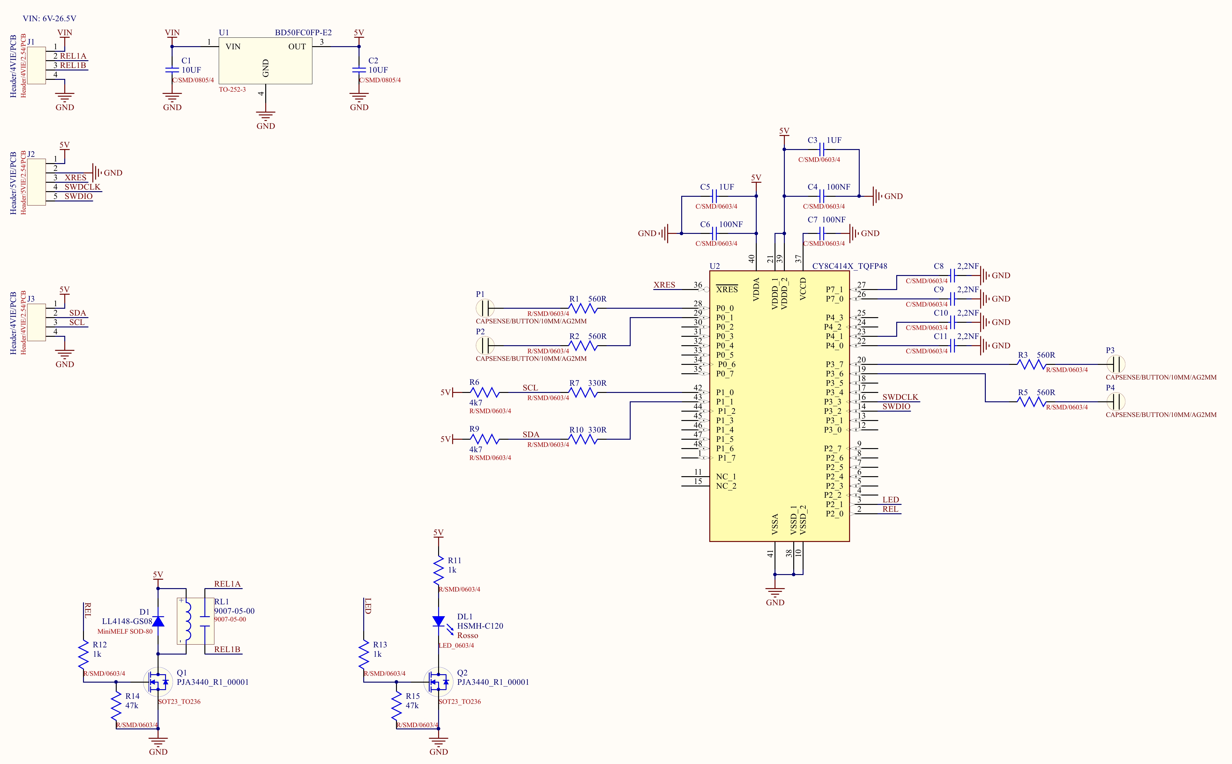
On the board I have inserted a relay to indicate the state of alarm to the electronics of the remote control. The relay is always on and when the hand is no longer detected, the relay is turned off.
I inserted a DC/DC converter so that the board can be powered with extended voltage range: 6-26.5V.
I connected a LED (see the following figure) to show the state of the relay.
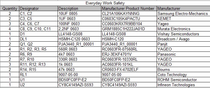
First I did some experiments with an evaluation board that I purchased previously. After understanding how it worked, I have decided to create a custom board. First of all I have selected the microcontroller, then I have designed the electrical scheme and made the 3D drawing of the handle and finally I have designed the PCB and assembled the components.
For the project I have chosen the CY8C4149AZI-S593 microcontroller, available and ready for delivery on Mouser.
For the sensing I have thought of inserting four CSD CapSense buttons and starting from an example project.
In ModusToolbox I have created a new project and selected the kit: CY8CKIT-041S-MAX and then I have clicked on Next.
On the next screen I have selected the Template Application->Sensing->MSC CAPSENSE CSD Button Tuning, I have given the name to the project: "Everyday Work Safety" and I have clicked on Create.
I have opened the project and I did the Build for a check.
Then I have changed the microcontroller in Device Configuration 4.0
I have clicked on File->New
I have overwritten the file name design.mosus; in the field “Device” I have inserted the model of the microcontroller chosen for my project and finally I have clicked OK.
Obviously I had to reconfigure the microcontroller.
Then, keeping in mind the electrical scheme of the project, I have started the reconfiguration.
First I have configured the system.
Then I have configured the Peripheral-Clocks.
It is very important to use the same names as the example project, otherwise it will be necessary to change them also in the source code.
On the page Peripheral it is necessary to configure the EZI2C peripherals (for the CapSense tuner) and CapSense.
I have clicked on Launch CapSense Configurator and configured the four buttons.
I have clicked on Save and then I have closed the window from the X, returning to the window of Device Configurator.
I have completed the configuration of theCapSense peripheral in this way:
Finally, in the Pins window I have set the pins for the control of the relay and LED.
I have closed the Device configurator and performed the Build of the project.
I had this error:
ERROR:Current Devices: CY8C4149AZI-S593
ERROR:Expected Devices: CY8C4149AZI-S598
Then with the search function I have changed the Device in the files of the project in which the old Device was still present.
Then I have commented this line of codes:
//        led_control();
//        Cy_GPIO_Inv(CYBSP_SENSE_SCAN_RATE_PORT, CYBSP_SENSE_SCAN_RATE_NUM);
//        Cy_GPIO_Write(CYBSP_LED_BTN0_PORT, CYBSP_LED_BTN0_NUM, CYBSP_LED_STATE_ON);
//        Cy_GPIO_Write(CYBSP_LED_BTN0_PORT, CYBSP_LED_BTN0_NUM, CYBSP_LED_STATE_OFF);
//        Cy_GPIO_Write(CYBSP_LED_BTN1_PORT, CYBSP_LED_BTN1_NUM, CYBSP_LED_STATE_ON);
//        Cy_GPIO_Write(CYBSP_LED_BTN1_PORT, CYBSP_LED_BTN1_NUM, CYBSP_LED_STATE_OFF);
And the Build was successful:
Build Finished. 0 errors, 0 warnings.At this point I have connected the MINIPROG4 to my board, by connecting both the SWD connector and the SCL and SDA pins of the 6x2 Connector.
After that I have opened the CapSense Tuner 5.0.
In the following figures it is possible to see the tuning sequence of the 4 buttons that I performed. The sequence from Figure 3 to Figure 7 must be repeated for each button. I did the signal acquisition phase with a work glove. The latest figure shows the final test of the buttons while keeping the handle with the work glove.
After that I have closed the CapSense Tuner 5.0.
Finally I have modified some lines of code.
I have eliminated the led_control() function;
I have created the relay_control() function and inserted it in the main.c
/*******************************************************************************
* Function Name: relay_control
********************************************************************************
* Summary:
* Turning Relay ON/OFF based on button status
*
*******************************************************************************/
static void relay_control(void)
{
    if((MSC_CAPSENSE_WIDGET_INACTIVE == Cy_CapSense_IsWidgetActive(CY_CAPSENSE_BUTTON0_WDGT_ID, &cy_capsense_context)) &&
        (MSC_CAPSENSE_WIDGET_INACTIVE == Cy_CapSense_IsWidgetActive(CY_CAPSENSE_BUTTON1_WDGT_ID, &cy_capsense_context)) &&
        (MSC_CAPSENSE_WIDGET_INACTIVE == Cy_CapSense_IsWidgetActive(CY_CAPSENSE_BUTTON2_WDGT_ID, &cy_capsense_context)) &&
        (MSC_CAPSENSE_WIDGET_INACTIVE == Cy_CapSense_IsWidgetActive(CY_CAPSENSE_BUTTON3_WDGT_ID, &cy_capsense_context)))
    {
        Cy_GPIO_Write(REL_PORT, REL_NUM, OFF);
    }
    else
    {
        Cy_GPIO_Write(REL_PORT, REL_NUM, ON);
    }
}
This function turns off the relay if at least a button detects the hand.
Also, in order not to have compilation errors I have declared the function at the beginning in the main.c:
static void relay_control(void);and defined these values:
#define ON          (0U)
#define OFF         (1U)
In the main loop I have inserted the call to the relay function:
/* Turns Relay ON/OFF based on button status */
relay_control();
Finally I have compiled and programmed the microcontroller.
Case and AssemblingAfter assembling the electronic components on the PCB and verified the operation, I have printed the test handle of the remote control with my 3D printer. Unfortunately the whole handle did not enter the plate of my printer, and therefore I have had to print it in two pieces. Attached to the project I have inserted all the 3D files for both single and two parts printing, together with the PCB 3D (uploaded to Hackster and also on Sketchfab).
I have used hot glue to assemble the two parts and the PCB; here are some photos.
This security system could be tested in a company that produces remote control devices, or another possible option could be that Infineon makes my project an evaluation board. 😀
That's AllIf you have any questions or suggestions don't hesitate to leave a comment below.


Comments
Please log in or sign up to comment.