Stepper motors, due to their unique design, can be controlled to a high degree of accuracy without any feedback mechanisms. The shaft of a stepper, mounted with a series of magnets, is controlled by a series of electromagnetic coils that are charged positively and negatively in a specific sequence, precisely moving it forward or backward in small "steps".
There are two types of steppers, Unipolars and Bipolars, and it is very important to know which type you are working with. For each of the motors, there is a different circuit. The example code will control both kinds of motors. See the unipolar and bipolar motor schematics for information on how to wire up your motor.
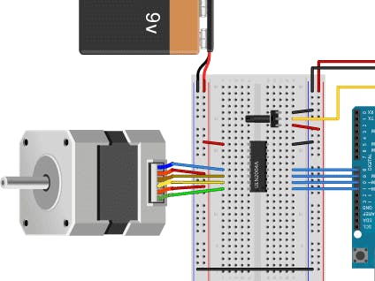
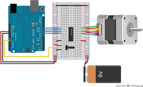
In this example, a potentiometer (or other sensor) on analog input 0 is used to control the movement of a stepper motor using the Arduino Stepper Library. The stepper is controlled by with digital pins 8, 9, 10, and 11 for either unipolar or bipolar motors.
The Arduino board will connect to a U2004 Darlington Array if you're using a unipolar stepper or a SN754410NE H-Bridge if you have a bipolar motor.
For more information about the differences of the two types, please take a look at Tom Igoe's page on stepper motors.


_ztBMuBhMHo.jpg?auto=compress%2Cformat&w=48&h=48&fit=fill&bg=ffffff)


Comments
Please log in or sign up to comment.