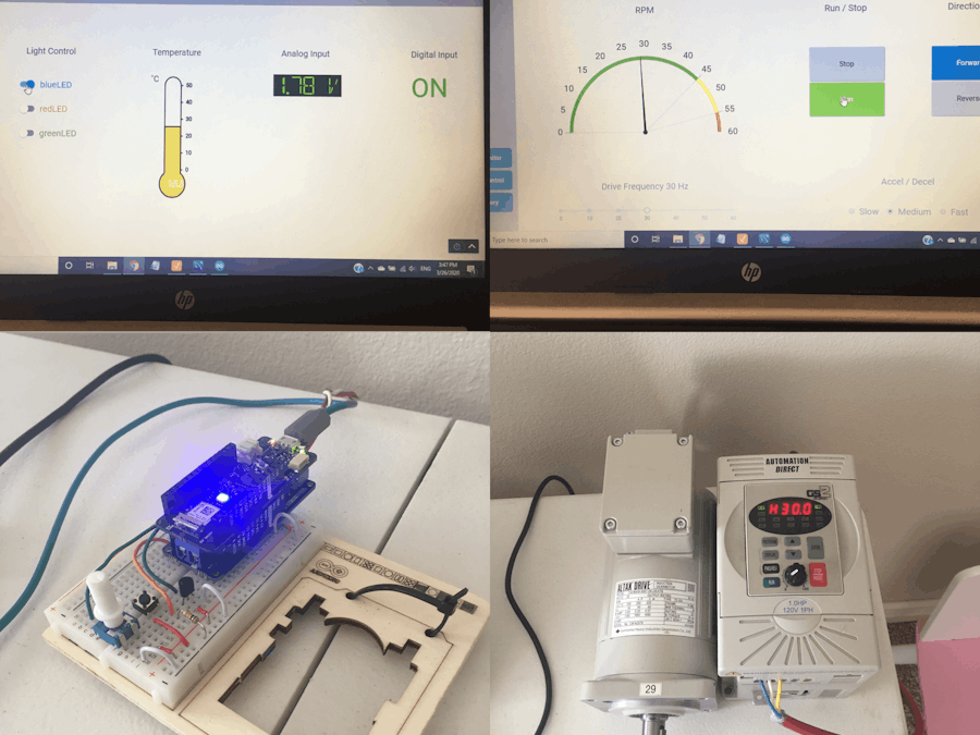
I started studying how to configure Ignition SCADA for a project at work and I wanted to have a real source of data to work with before the project starts. Ignition includes a PLC simulator but I found that un-exciting. So I decided to see if Ignition could interface with an Arduino and the result was a resounding yes.
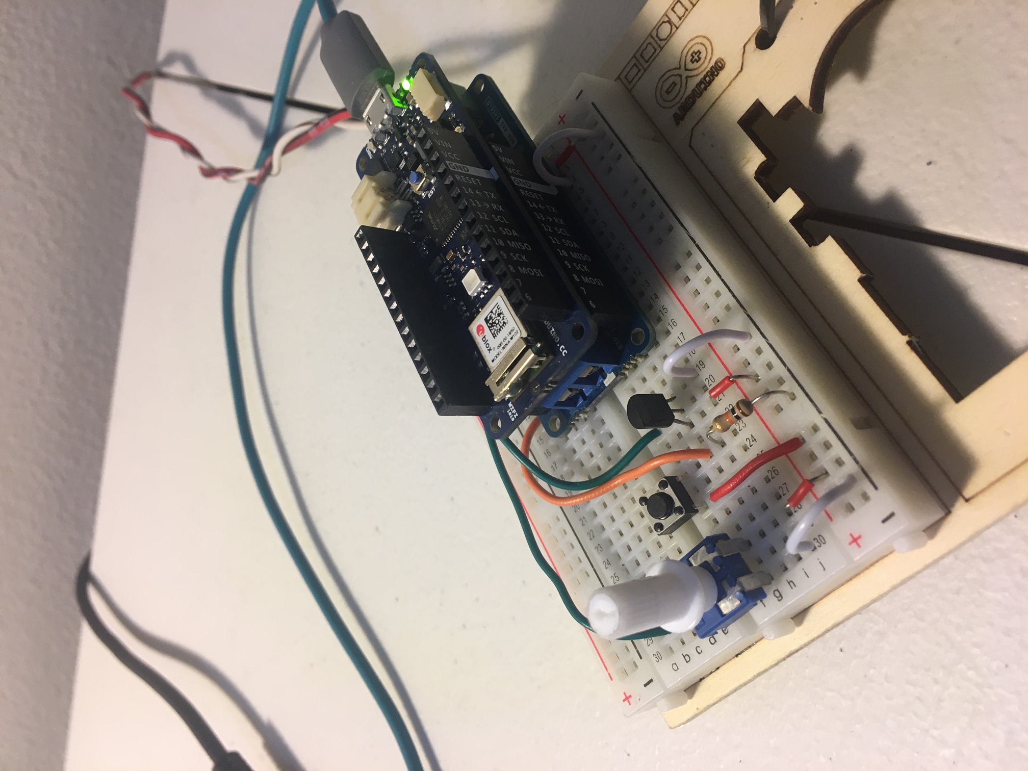
This project will show you how to connect a MKR WiFi 1010 + MKR RS 485 Shield to Ignition using the Modbus driver in Ignition. A VFD is shown in this example but if you don't have a VFD you can remove that part from the code and just work with the other data which is: on-board RGB LED, push button, temp sensor, and potentiometer.
The base of the code is the example Modbus TCP server and my VFD control example which is build of off the Modbus RTU client example provided in Arduino IDE if you have the Modbus library installed.
The key functions of the code are as follows:
1) Set the board to be a Modbus TCP server (slave) for Ignition
2) Set the board to be a Modbus RTU Client (master) for the VFD
3) Acquire local data from a potentiometer, push button, and temp sensor
If you're not familiar with Modbus, one phrase that's always helped me understand it is "shared" addresses. For example in this case Ignition can write a "1" or "0" to a memory address in the board. Then in order to know if the VFD should run, the code takes whatever is in that memory address and writes it to another shared address in the VFD. If this value is always "0" the drive stays stopped, but once a "1" is written the drive starts to move given other parameters such as desired frequency are correct.
One thing to be mindful of is that pins A5 and A6 are used for controlling the RS 485 Shield RE/DE so they cannot be used for anything else. I spent a few hours struggling with that so hopefully if you're trying to replicate this you have read this section!
Ignition is really great because you can download it and start learning for free. Below are some key things you need to know in order to configure the device section of Ignition.
When you first boot up your board, getthe IP address using serial monitor.
Of course your board and Ignition instance must be on compatible IP addresses (i.e. you can do CMD --> ping 192.168..xx.xxx and get a reply).
Enter the addresses. Key point is that hex addresses (i.e. 0x01) require the "Radix" setting be 16.
In the arduino modbus library and for use with Ignition, a coil (a single bit) and a holding register (16 bits) can both have the same address value i.e. two of them can be "0" but based on how they are implemented in the controller they are two physically different addresses.
If you want to connect to your Ignition gateway from a different PC in your home, you have to setup the self signature SSL certificate and open up inbound and outbound traffic for port 8088 in your firewall.
Here is the link to a video which quickly shows things working.
v


Comments
Please log in or sign up to comment.