


Hardware components | ||||||
 |
| × | 1 | |||
 |
| × | 1 | |||
 |
| × | 1 | |||
Software apps and online services | ||||||
 |
| |||||
| ||||||
When I asked for ADC ATtiny on the web, I found a lot of different things, so, this tiny tutorial for ATtiny is only an example for using serial communication and 10-bit ADC (but it'll be an explanation for 8-bit, not Arduino Sketch).
First we need to remember:
- 8 Bit = 0 - 255 Value Range
- 10 Bit=0 - 1024 Value Range
The most important part in the ADC config are these variables.
 ADMUX =
           (0 << ADLAR) |     // do not left shift result (for 10-bit values)
           (0 << REFS2) |     // Sets ref. voltage to internal 1.1V, bit 2
           (1 << REFS1) |     // Sets ref. voltage to internal 1.1V, bit 1
           (0 << REFS0) |     // Sets ref. voltage to internal 1.1V, bit 0
           (0 << MUX3)  |     // use ADC2 for input (PB4), MUX bit 3
           (0 << MUX2)  |     // use ADC2 for input (PB4), MUX bit 2
           (1 << MUX1)  |     // use ADC2 for input (PB4), MUX bit 1
           (0 << MUX0);       // use ADC2 for input (PB4), MUX bit 0
 ADCSRA =
           (1 << ADEN)  |     // Enable ADC
           (1 << ADPS2) |     // set prescaler to 64, bit 2
           (1 << ADPS1) |     // set prescaler to 64, bit 1
           (1 << ADPS0);      // set prescaler to 64, bit 0
Those variables establish the bits of the ADC process, based on reference voltage and the prescalizer.
In this tutorial we go to use a 10-bit ADC. For an 8-bit ADC, we would need to use the following values:
 ADMUX =
           (1 << ADLAR) |     // left shift result
           (0 << REFS1) |     // Sets ref. voltage to VCC, bit 1
           (0 << REFS0) |     // Sets ref. voltage to VCC, bit 0
           (0 << MUX3)  |     // use ADC2 for input (PB4), MUX bit 3
           (0 << MUX2)  |     // use ADC2 for input (PB4), MUX bit 2
           (1 << MUX1)  |     // use ADC2 for input (PB4), MUX bit 1
           (0 << MUX0);       // use ADC2 for input (PB4), MUX bit 0
 ADCSRA =
           (1 << ADEN)  |     // Enable ADC
           (1 << ADPS2) |     // set prescaler to 64, bit 2
           (1 << ADPS1) |     // set prescaler to 64, bit 1
           (0 << ADPS0);      // set prescaler to 64, bit 0
The next part of our code is a comparison for the conversion and finally we send it all through serial.
ADCTo make the lecture of our ADC, we need a comparison. For 10-bit ADC the comparison is this:
uint8_t adc_lobyte;
uint16_t raw_adc;
void setup()
{
[...]
}
int var=0;
void loop()
{
 ADCSRA |= (1 << ADSC);           // start ADC measurement
 adc_lobyte = ADCL;               // get the sample value from ADCL
 raw_adc = ADCH<<8 | adc_lobyte;  // add lobyte and hibyte //raw_adc are our measure
 delay(10);
}
For 8-bit ADC, it is simpler:
void setup()
{
[...]
}
int var=0;
void loop()
{
 ADCSRA |= (1 << ADSC);           // start ADC measurement
 var = ADCH;                      // get the sample value from ADCH
 delay(10);
}
We use two libraries and declare our serial in a variable.
#include <SoftSerial.h>
#include <TinyPinChange.h>
SoftSerial ASerial(2, 3);  // RX, TX
The Setup part only begins it. Example:
void setup()
{
 ASerial.begin(9600);
}
And now we are going to use the serial like other serial communication in Arduino:
ASerial.println(myADC);
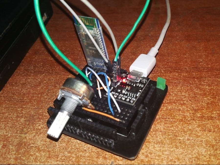
We have an Arduino Sketch for reading the 10-bit ADC in the PB4 pin of the ATtiny. The RXTX pins are connected to a HC-05 Bluetooth module. (You can use other options like USB-Serial converter.) And we use a simple Potentiometer for the analog value.
In an Android Device, we use an application called "Bluetooth Terminal HC-05", but this is nothing sophisticated. It is just a terminal like PuTTY or any other, and this is the result.
Ta daaa! That's all.
I took part of the info from the next website, here is the complex cousin of this sketch: https://www.marcelpost.com/wiki/index.php/ATtiny85_ADC


Comments
Please log in or sign up to comment.