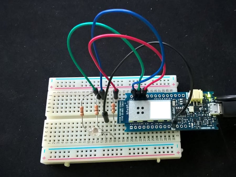
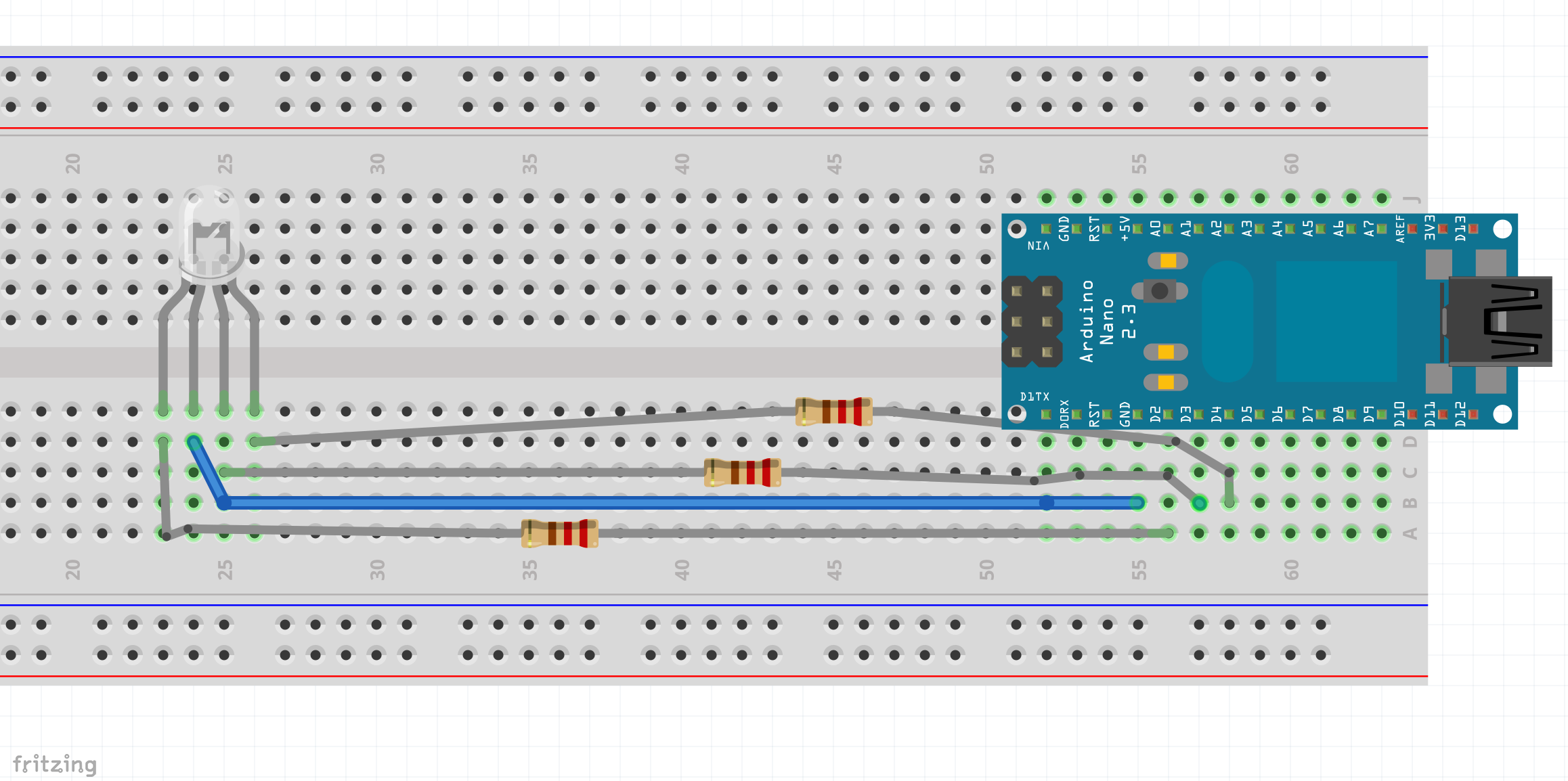
Using MKR1000 to control an RGB LED device.
In our shortened example we will use a single RGB LED. In real world we would attach the RGB channels to a RGB Amplified or other like device. We are hoping to demonstrate how you can start using Arduino MKR1000 board as a remote helping hand to do tasks for you. For example in my home I want to move this into a soffit with existing RGB LED light strip that is today controlled by a IR and is a chore to hide.
Step 1 - Stand on Shoulders of Giants
First you will need to follow this steps to completion of where you would have a web page ready and onboard LED listening to your commands. If you run into trouble with your board and PC like I did this is the place to get pointers.
Arduino MKR1000 Getting Started by Charif Mahmoudi
https://www.hackster.io/charifmahmoudi/arduino-mkr1000-getting-started-08bb4a
Note how to listen to the IP address in the Serial Monitor - in my case the IP address stayed the same, your specific router might change.
Now that you know your board and PC are all working together. You can now control this device via your home network - we will build on top of this concept further and send PWD commands to an RGB LED and setup scene triggers.
Keep everything open - we will build on this previous sample and add RGB LED and add the Web page controls for each color.
Step 2 - Improve by Wiring up RGB LED
I used the concepts from just about any standard RGB LED concept you can find online.
RBG LED Color Chooser
http://playground.arduino.cc/Main/RGBLEDPWM
Same goes for wiring. There are many examples of this specific to your LED.
On the board I used Digital Pin 2 , 3 & 4 as they were listed as PWM in the official spec for my MKR1000 board as follows:
Step 3 - Improve by Writing Code for RGB LED
We will build on and add the Web page controls for each color.
First we add declarations for the RGB PINs.
// Init the Pins used for PWM
int redPin = 2;
int greenPin = 3;
int bluePin = 4;
Then we initialize those PINs for OUTPUT.
pinMode(redPin, OUTPUT);pinMode(greenPin, OUTPUT);
pinMode(bluePin, OUTPUT);
And finally we add a couple more URLs in the Web output.
client.print("<hr>");
client.print("Click <a href=\"/Movie\">here</a> turn on scene Movie<br>");
client.print("Click <a href=\"/Reading\">here</a> turn on scene Reading<br>");

client.print("<hr>");
client.print("Click <a href=\"/RESET\">here</a> RESET ALL<br>");
Then add the handler for the new Scenes.
if (currentLine.endsWith("GET /Movie")) {
	analogWrite(redPin, 128);
	analogWrite(greenPin, 0);
	analogWrite(bluePin, 50);
}
if (currentLine.endsWith("GET /Reading")) {
	analogWrite(redPin, 255);
	analogWrite(greenPin, 128);
	analogWrite(bluePin, 255);
}
if (currentLine.endsWith("GET /RESET")) {
	analogWrite(bluePin, 0);
	analogWrite(greenPin, 0);
	analogWrite(redPin, 0);
	digitalWrite(ledpin, LOW);
}
Step 4 - Create an App or use Browser
The UWP Windows 10 Mobile app can be built to quickly call up these scenes with a push of a button, when your device is on the same network. A HTTP GET command to your IP Address with the scene or reset command is all it takes. In the interest of time web page pointed to the IP address from Step 1 is all that is needed to get going.
Conclusion & Next Steps
As you can see sometimes it takes tinkering with some new tech and adding your own implementation. For me it was starting with an outcome and seeking an easy solution to address my mechanics of remotely controlling the RGB from a distance problem. I hope you learned from this example and can benefit from this experience in your own creations.
Hack on!


Comments
Please log in or sign up to comment.