

Hardware components | ||||||
_ztBMuBhMHo.jpg?auto=compress%2Cformat&w=48&h=48&fit=fill&bg=ffffff) |
| × | 1 | |||
 |
| × | 1 | |||
 |
| × | 1 | |||
 |
| × | 1 | |||
Software apps and online services | ||||||
 |
| |||||
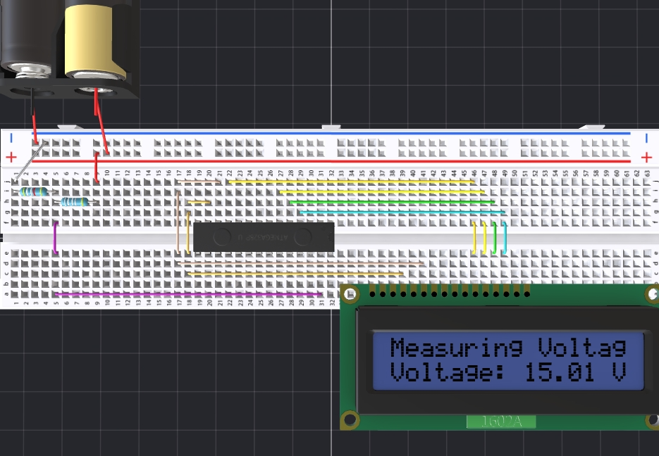
This tutorial will guide you through creating a 3D simulation of a battery-level detection and display system using a popular online platform like Tinkercad or similar tools. We will use a virtual ATMEGA328P microcontroller, an LCD1602 display, and a voltage divider circuit to simulate the real-world scenario.
Key Components:- ATMEGA328P Microcontroller: The brain of the system, isresponsible for reading the battery voltage and controlling the LCD display.
- LCD1602 Display: A 16x2 character LCD used to display the measured battery voltage.
- Voltage Divider: A simple circuit consisting of two resistors (R1 and R2) used to reduce the battery voltage to a level safe for the microcontroller's analog input.
- Battery: Simulated as a voltage source in the 3D environment.
- Place two resistors (R1 = 100kΩ and R2 = 49.9kΩ) in series.
- Connect one end of the series to the positive terminal of the simulated battery.
- Connect the junction between the two resistors to the analog input pin (A4) of the ATMEGA328P.
- Connect the other end of the series to the ground.
- Refer to the datasheet of the LCD1602 to identify the pin connections for data (D4-D7), enable (EN), register select (RS), and power supply.
- Connect these pins to the appropriate digital pins on the ATMEGA328P according to the datasheet and the provided code.
- Connect the LCD's power supply and ground to the appropriate voltage sources in the simulation environment
- Connect the ATMEGA328P to the power supply (5V) and ground.
- Connect the necessary ground connections between the components.
- Upload the provided Arduino code to the virtual ATMEGA328P microcontroller within the simulation environment.
- Run the simulation.
- Observe the LCD display. It should display the measured battery voltage in real-time.
- Adjust the simulated battery voltage to verify the accuracy of the voltage reading on the LCD.
- Visual Learning: Provides a visual representation of the circuit and its components.
- Interactive Exploration: Allows for experimentation by modifying component values and observing the effects.
- Safety: Eliminates the risk of damaging components during physical prototyping.
- Cost-Effectiveness: Simulates the circuit without the need for actual hardware.
Simulation details here: https://www.pcbx.com/sim/?id=e1997d36e4f84f1eae6795588b4809d4
This tutorial provides a basic framework for simulating a battery-level detection and display system. By following these steps and exploring further, you can gain a deeper understanding of the underlying principles and experiment with different configurations.
Join the PCBX community to simulate your own projects
https://www.pcbx.com/forum?mtm_campaign=E&mtm_kwd=hack
Register now to get your first Free PCB&PCBA coupon
https://www.pcbx.com/?mtm_campaign=E&mtm_kwd=BD
While the 3D simulation feature is still a work in progress, we would love to hear your suggestions and expectations. It's an open-source community; any sharing and feedback is welcome.
Your feedback will help our engineering team enhance the platform and better serve our users.T


Comments