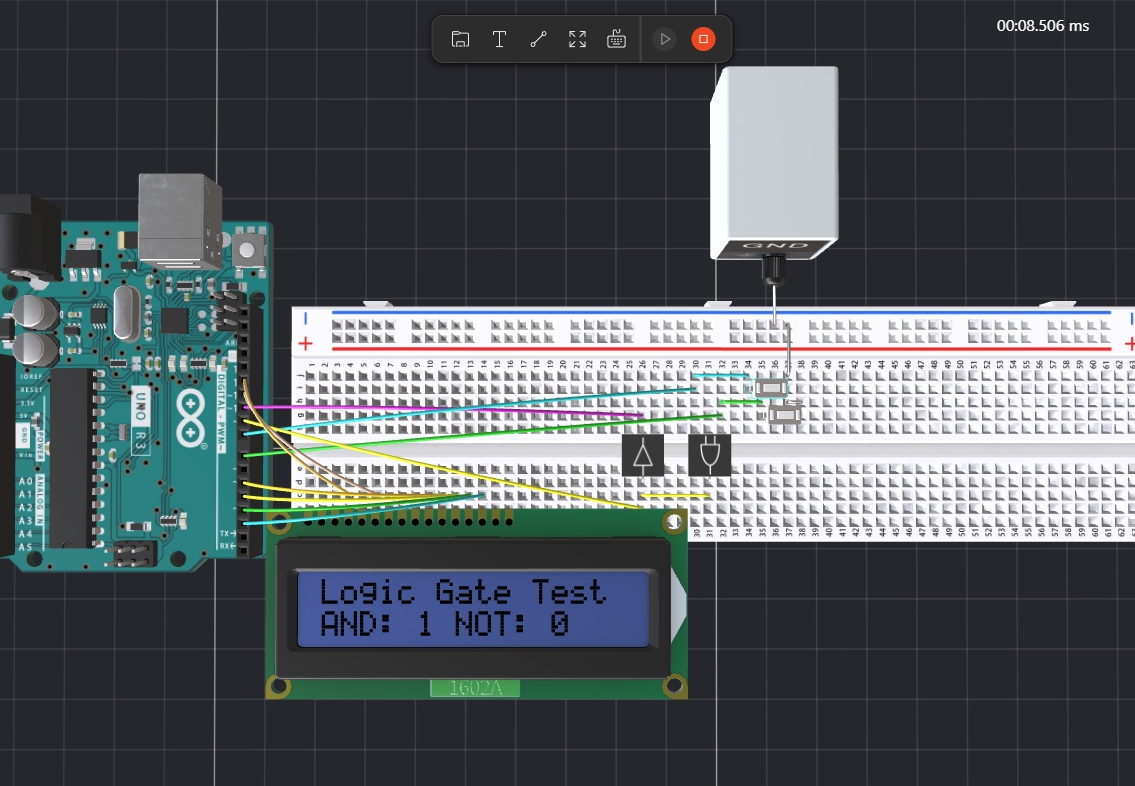
Introduction:
In this tutorial, we will guide you through the process of creating a simple logic gate tester using an Arduino. We will set up an LCD display to show the results of the AND and NOT logic gates based on the input from two buttons. This project is a great way to learn about basic electronics, programming, and the workings of logic gates.
Components Needed- Arduino board (e.g., Arduino Uno)
- 16x2 LCD display
- 2 Push buttons
- Breadboard and jumper wires
- 220-ohm resistors (for pull-down configuration)
LCD Connections:
Connect the LCD pins to the Arduino as follows:
- LCD RS to pin 12
- LCD E to pin 11
- LCD D4 to pin 5
- LCD D5 to pin 4
- LCD D6 to pin 3
- LCD D7 to pin 2
- LCD VSS to Ground
- LCD VDD to +5V
- Connect a 220-ohm resistor from the V0 (contrast pin) to the ground.
- Connect the LCD pins to the Arduino as follows:LCD RS to pin 12LCD E to pin 11LCD D4 to pin 5LCD D5 to pin 4LCD D6 to pin 3LCD D7 to pin 2LCD VSS to GroundLCD VDD to +5VConnect a 220-ohm resistor from the V0 (contrast pin) to the ground.
- LCD Connections:Connect the LCD pins to the Arduino as follows:LCD RS to pin 12LCD E to pin 11LCD D4 to pin 5LCD D5 to pin 4LCD D6 to pin 3LCD D7 to pin 2LCD VSS to GroundLCD VDD to +5VConnect a 220-ohm resistor from the V0 (contrast pin) to the ground.
Button Connections:
- Connect Button 1 to pin 7 and the other side of the button to ground.
- Connect Button 2 to pin 8 and the other side of the button to ground.
- Button Connections:Connect Button 1 to pin 7 and the other side of the button to ground.Connect Button 2 to pin 8 and the other side of the button to theground.
Logic Gate Output Pins:
- Connect pin 9 (AND output) to an LED or the next circuit stage.
- Connect pin 10 (NOT output) to another LED or circuit stage.
- Logic Gate Output Pins:Connect pin 9 (AND output) to an LED or the next circuit stage.Connect pin 10 (NOT output) to another LED or circuit stage.
Here are the project link so you can do the online operation to have a test
https://www.pcbx.com/forum-detail/277f270e3df747549202a6e22ce77bc5
ConclusionThis tutorial detailed the setup and coding of a basic logic gate tester using an Arduino and an LCD display. You can extend this project by adding more logic gates, such as OR, NAND, or NOR, and displaying their results on the same LCD. Experimenting further with this project will deepen your understanding of logic operations and Arduino programming. Happy coding!
Join the PCBX community to simulate your own projects
https://www.pcbx.com/forum?mtm_campaign=E&mtm_kwd=hack
Register now to get your first Free PCB&PCBA coupon
https://www.pcbx.com/?mtm_campaign=E&mtm_kwd=BD
While the 3D simulation feature is still a work in progress, we would love to hear your suggestions and expectations. It's an open-source community; any sharing and feedback is welcome.
Your feedback will help our engineering team enhance the platform and better serve our users.
Thank you!


_ztBMuBhMHo.jpg?auto=compress%2Cformat&w=48&h=48&fit=fill&bg=ffffff)


Comments
Please log in or sign up to comment.