


Hardware components | ||||||
_ztBMuBhMHo.jpg?auto=compress%2Cformat&w=48&h=48&fit=fill&bg=ffffff) |
| × | 1 | |||
| × | 1 | ||||
 |
| × | 1 | |||
 |
| × | 1 | |||
 |
| × | 1 | |||
Software apps and online services | ||||||
 |
| |||||
 |
| |||||
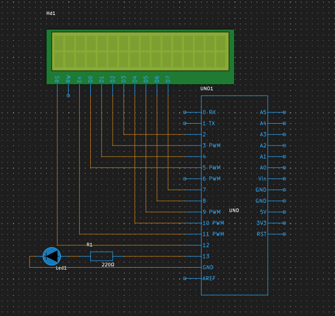
Connections:
LCD to Arduino:
RS (Register Select) pin connected to Arduino Digital Pin 12.
E (Enable) pin connected to Arduino Digital Pin 11.
D0-D3 (Data pins) connected to Arduino Digital Pins 5-2 respectively.
D4-D7 (Data pins) connected to Arduino Digital Pins 10-7 respectively.
LED:
Positive leg connected to Arduino Digital Pin 13.
The negative leg is connected through the 220Ω resistor to the Arduino's Ground (GND).
Code Functionality:
Initializes LCD, and sets LED as output. Clears LCD, displays "Counting to 100...". Counts 1-100, displays count, blinks LED for multiples of three, counts blinks. After counting, shows "LED Blinks: X" and halts.
After counting, shows "LED Blinks: X" and halts: Once the count reaches 100, the program stops incrementing and displays the total number of LED blinks on the LCD. The program then halts, and the final message remains on the display.
Simulation in action:Project Link: https://www.pcbx.com/sim?id=6866cc2e8da3440288b2b2d9dcc7a493&type=share
Simulate your project here: https://www.pcbx.com/forum?mtm_campaign=E&mtm_kwd=hack


Comments